Introduction
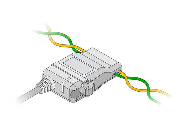
The IOX-CLAMP allows a read-only connection to the vehicle CAN bus using a capacitive clamp to get vehicle data without electrical contact, thereby preventing vehicle interference and not voiding the manufacturer's warranty. It automatically detects polarity, baud rate, and CAN bus protocol. No configuration is required.
Recommended Tools & Consumables
-
-
Before starting the installation, ensure that the GO device is unplugged from the vehicle.
-
-
-
If a GO Device is already installed, unplug the GO device from the vehicle before preceding with the next steps.
-
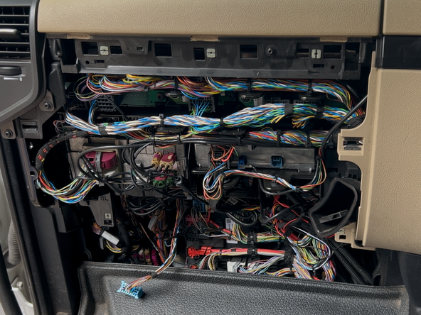
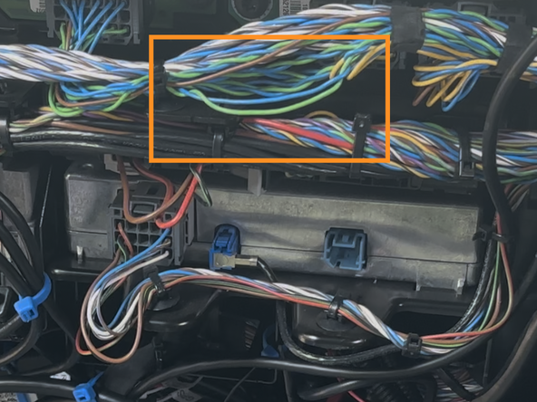
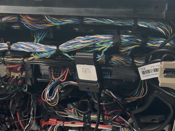
Identify the intended installation location and wiring for the IOX-CLAMP.
-
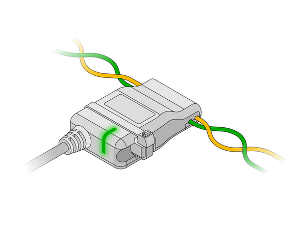
If the wires are twisted, slightly untwist them first.
-
Refer to the CAN Bus Location Guide for a list of vehicle specific wire locations.
-
-
-
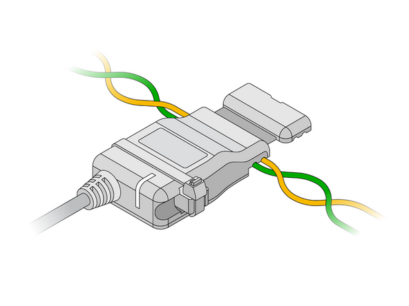
Open the clamp and insert the wires into either of the device cavities.
-
Ensure the wires are seated in the grooves of the clamp.
-
The IOX-CLAMP features automatic polarity detection, allowing either wire to be inserted into either of the clamp's cavities.
-
Never cut, extend or modify the vehicle CAN bus wires.
-
Do not connect the clamp to any wires from the CAN bus CAN-A (pin A4 and A8) of a tachograph, because most of the parameters cannot be obtained via these wires.
-
-
-
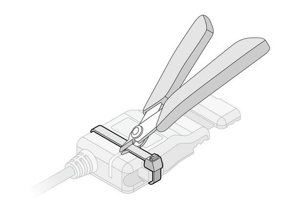
The IOX-CLAMP comes with a termination shunt installed in the expansion port. If you need to install more than one IOX in a daisy chain, you must remove the shunt from each device in the line, except for the last IOX connected.
-
The shunt must remain in the last IOX and be secured with a cable tie. The shunt in the last IOX ensures that the GO device detects and configures the IOX as effectively as possible.
-
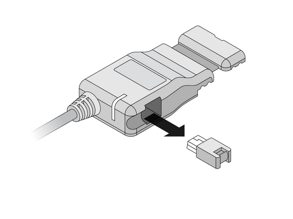
Remove the termination shunt located on one of its harness branches by cutting the cable tie and unplugging the shunt.
-
-
-
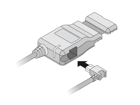
Remove the expansion Port cover on the GO device.
-
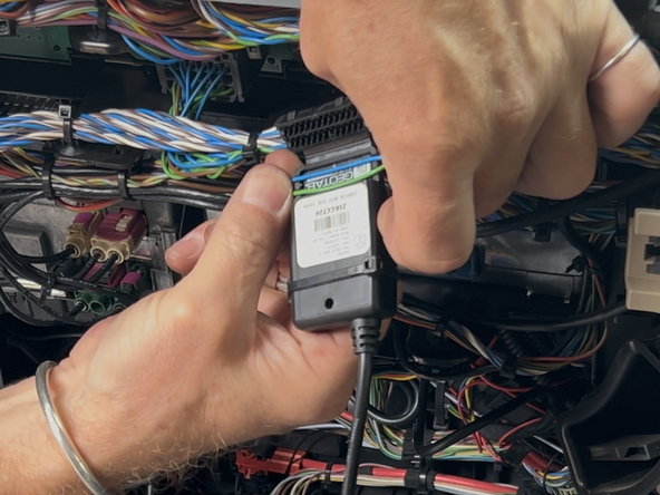
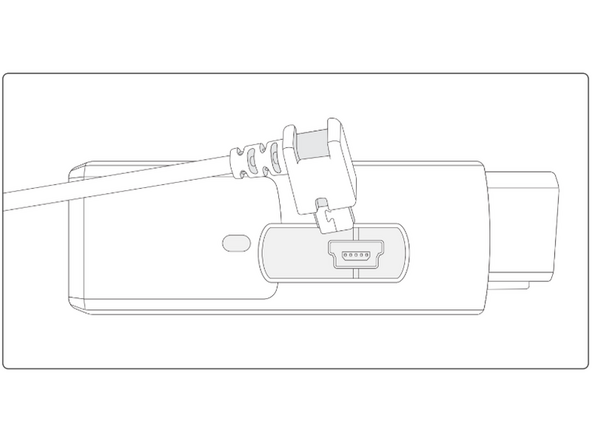
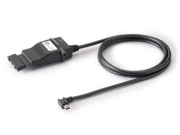
Plug in the 90° USB connector from the IOX-CLAMP into the GO device.
-
The USB connector must be inserted in the orientation displayed in the image to the right, with the 90° bend facing away from the GO device’s OBD-II connector.
-
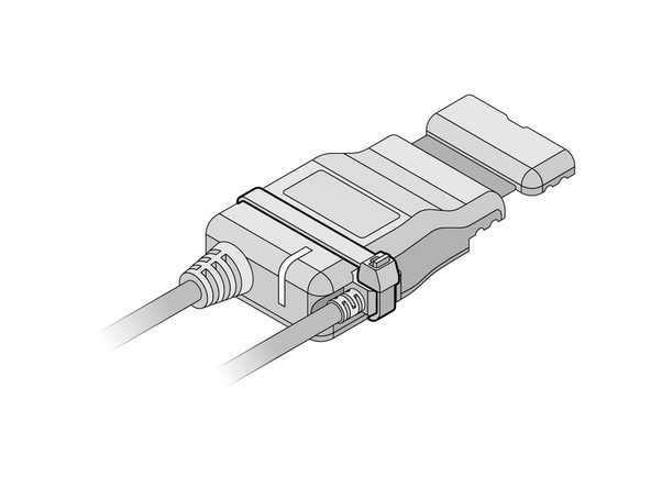
Secure the USB connector using a cable tie.
-
DO NOT OVER-TIGHTEN! the cable tie as this can damage the USB connector.
-
Trim any excess tie.
-
-
-
If you are installing the IOX-CLAMP in a vehicle that does not natively support the GO device, a 3-wire harness must be used to install the GO device. Refer to the HRN-CW03K3 guide for installation instructions.
-
If the IOX-CLAMP is being used to complement a GO device and a vehicle interface harness, then refer to the Harness page for installation instructions.
-
Refer to the Vehicle and Harness Register for a list of vehicle support via IOX-CLAMP.
-
-
-
The IOX-CLAMP device has a status LED that produces a series of blinks followed by a pause.
-
Ensure that the vehicle ignition / engine is ON when checking the installation status. If the LED is off, it may be due to a power problem or device failure.
-
Once the ignition / engine is on, after a few minutes, if the installation is correct, the light sequence should be SOLID Green.
-
If you see a different light sequence, refer to the IOX-CLAMP page for troubleshooting steps.
-
-
-
All in-vehicle devices and related cabling must be securely fastened and kept clear of all vehicle controls, airbags, and gas, brake and clutch pedals.
-
This requires the use of a cable tie when securing the device or any extension harness to the OBD connector, securing both sides of the harness. If you do not use a cable tie, vibration in the vehicle can lead to a loose connection which could cause the vehicle’s engine computer to fail, causing potential loss of vehicle control and serious injury.
-
Inspect devices and cabling regularly to ensure all devices and cabling continue to be securely attached.
-
If at any point after an in-vehicle device is installed a warning light illuminates on the vehicle dash or the vehicle stalls or has a marked drop in performance, shut off the engine, remove the device, and contact your reseller. Continuing to operate a vehicle with these symptoms can cause loss of vehicle control, and serious injury.
-
-
-
Navigate to one of the following:
-
-
-
Note that the following steps are for the public version of MyInstall.
-
If you have an installer MyAdmin account, use this link
-
This link is also accessible via the MyInstall Public page.
-
-
-
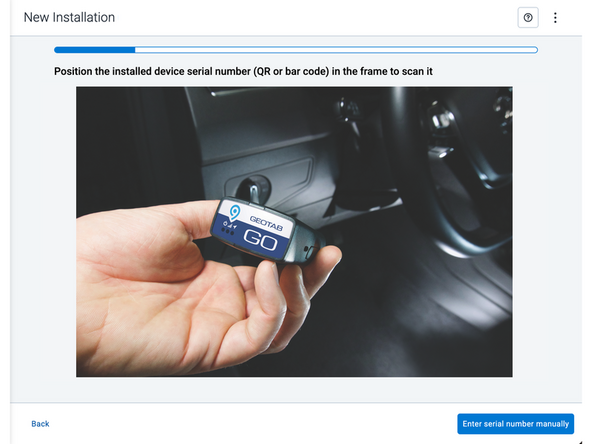
Two options are available to enter the device serial number:
-
Scan the device serial number (QR or barcode) using your mobile device.
-
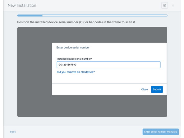
Press Enter serial number manually, enter the serial number, and then press Submit.
-
If you are also removing an old device, press Did you remove an old device? and then enter the removed device serial number.
-
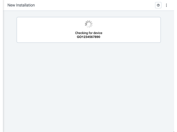
MyInstall takes a moment to check the device status.
-
-
-
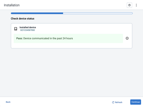
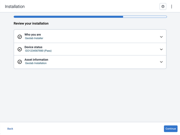
Installed device
-
Pass – The device has successfully communicated with the network in the last 24 hours.
-
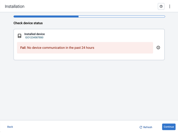
Fail – The device has not communicated with the network in the last 24 hours.
-
If the device status shows as FAILED, verify the LED status and turn the ignition / engine off and on again.
-
Press Refresh to check the status again.
-
Refer to the MyInstall User Guide for detailed instructions.
-
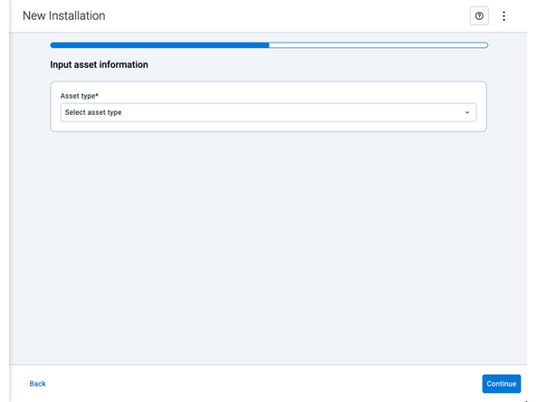
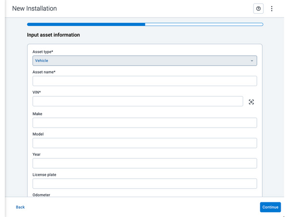
-
-
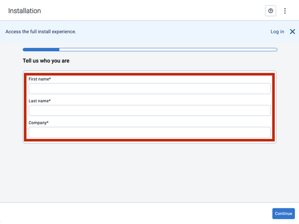
Asset name — Enter the vehicle or asset name. This field is mandatory.
-
VIN — Scan or enter the vehicle identification number (VIN). For scanning, select the scan icon [O] beside the field. This field is mandatory.
-
Make, Model, and Year — This information will be auto populated when you scan or enter a valid VIN. If it is not autopopulated, enter the information manually. NOTE: For some vehicle makes and models, the autopopulate option might not be possible.
-
License plate — Enter the vehicle license plate.
-
Odometer — Enter the vehicle odometer, and select the measurement unit (km or miles).
-
Engine hours — Enter the vehicle engine hours.
-
Camera ID (GO device only) — Scan or enter the installed camera identification (ID) number. NOTE: Depending on the camera type, the camera ID number can also be the camera’s International Mobile Equipment Identity (IMEI), or serial number. Select the information icon ⓘ to learn more about your camera’s ID number.
-
Work order reference — If applicable, enter a work reference number that is associated with the installation.
-
-
-
For the latest version of the Limitations of Use
-
Your in-vehicle devices must be kept clear of debris, water and other environmental contaminants. Failure to do so may result in units malfunctioning or short-circuiting, which can lead to a fire hazard and cause loss or serious injury.
-
This product does not contain any user-serviceable parts. Configuration, servicing, and repairs must only be made by an authorized reseller or installer. Unauthorized servicing of these products will void your product warranty.
-
The simplified EU declaration of conformity referred to in Article 10(9) shall be provided as follows:
-
Hereby, Geotab (Address: 2440 Winston Park Drive, Oakville, Ontario L6H 7V2, Canada, Phone number: 1 (877) 436-8221) declares that the radio equipment type ‘telematics device’ is in compliance with Directive 2014/53/EU. The full text of the EU declaration of conformity is available here.
-
WARNING: Cancer and Reproductive Harm
-