Introduction
This guide describes how to install a IOX-COLD & GO device into a vehicle with a Tachograph.
Recommended Tools & Consumables
Hardware & Accessories
Video Overview
-
-
WARNING! Only use Geotab telematics devices with Geotab-approved harnesses acquired from Geotab-authorized channels. Use of non-Geotab harnesses from unauthorized channels can cause serious safety risks, including fire, and can lead to serious personal injury and/or damage to the vehicle.
-
IMPORTANT: Always use a vehicle-specific harness when offered by Geotab or the vehicle manufacturer to avoid possible damage to the GO device. Some vehicles have multiple diagnostic connectors to choose from when installing a GO device.
-
For more information on Geotab harnesses and adapters, refer to the Harness Identification and Application & Harness Assessment Cheat Sheet & Geotab Truck Solution - Harness Identification and Application
-
If a longer length is required to facilitate installation, connect a straight harness to a T-harness. Ensure that the total harness length does not exceed 2 meters (6.5 feet), because this can compromise the integrity of the data and cause issues with the vehicle’s Engine Control Unit (ECU).
-
For more details on compliance information and applicable products, contact your Authorized Reseller.
-
-
-
WARNING! Some installations are not straightforward and must be completed by an Authorized Installer to ensure a secure installation.
-
An unsecure device can result in poor electric and/or data connections, which can lead to short circuits and fires or cause malfunctions of vehicle controls that can result in serious personal injury or significant damage to the vehicle. Some examples requiring professional installation from an Authorized Installer are:
-
The OBD port location is such that the device protrudes and interferes with entering or exiting the vehicle, or located where it could be inadvertently kicked or bumped during vehicle operation.
-
The device isn't fully secured and so may come loose with vibrations or accidental contact.
-
An electrical harness or additional wiring is required.
-
Vehicle mounting modifications are required to secure the device, i.e. removing of panels; deformed/damaged OBD connector; or physical damage to the electrical wiring.
-
The device does not power on and beep six times when first installed.
-
The installer questions their ability to complete a secure installation according to these instructions.
-
-
-
WARNING! Do not attempt to install, reconfigure, or remove any product from a vehicle while the vehicle is in motion or otherwise in operation. All installation, configuration, or removal must be done only in stationary vehicles which are securely parked.
-
Attempting to service devices while the vehicle is in motion could result in malfunctions or collisions, leading to death or serious personal injury.
-
-
-
Locate the diagnostic port in the vehicle
-
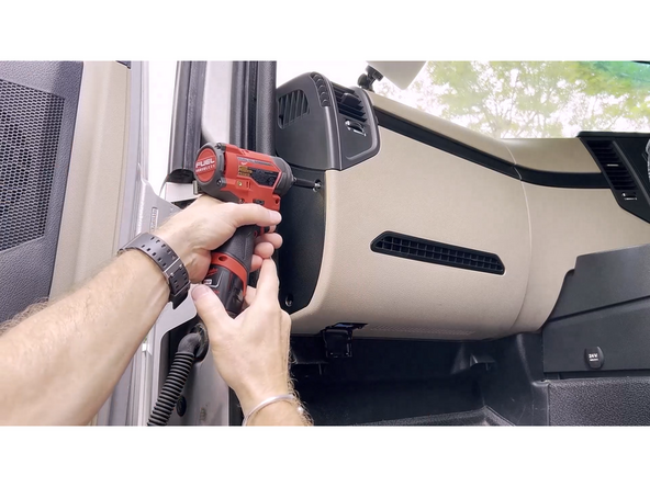
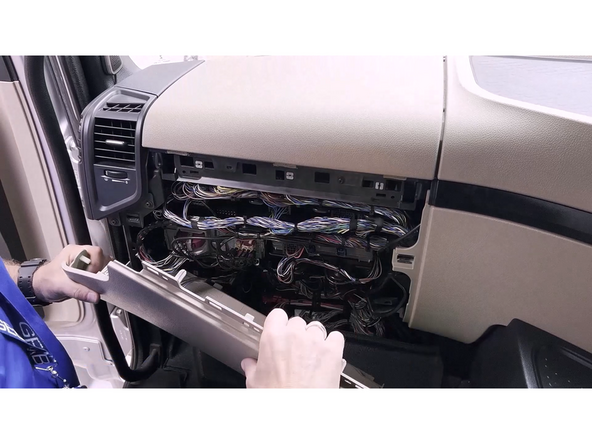
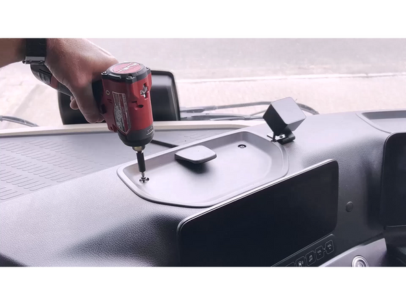
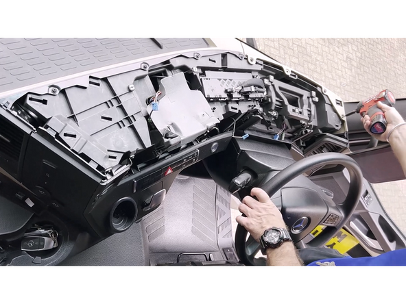
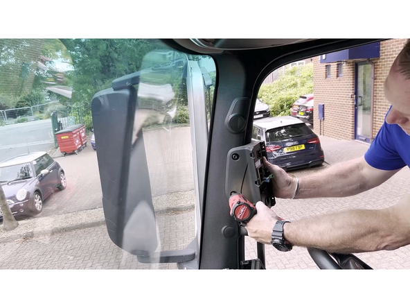
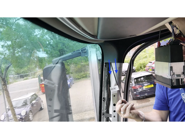
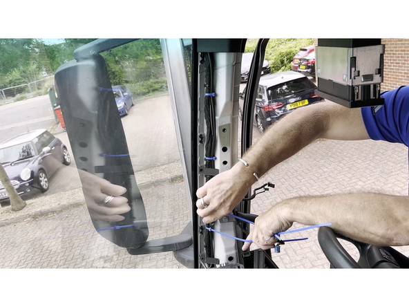
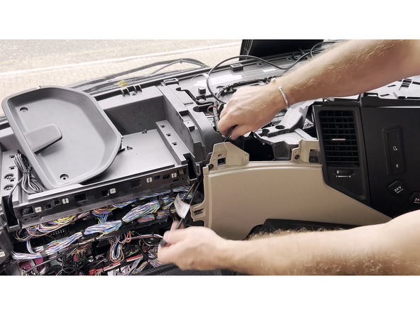
Start removing the dash panels required to access the vehicle’s diagnostic port. Take care not to damage any plastic clips or misplace any screws.
-
Depending on the vehicle, the amount of disassembly can vary.
-
-
-
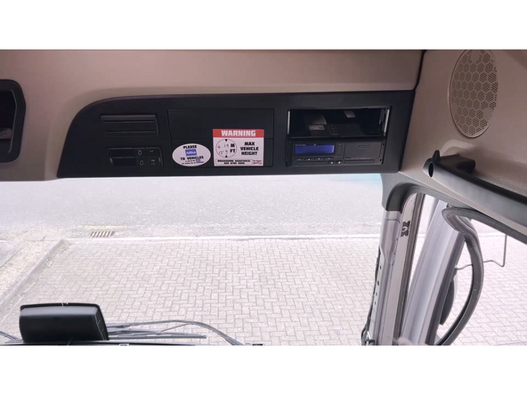
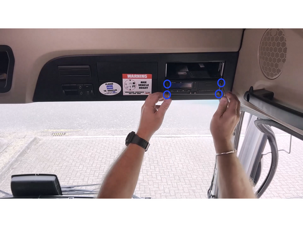
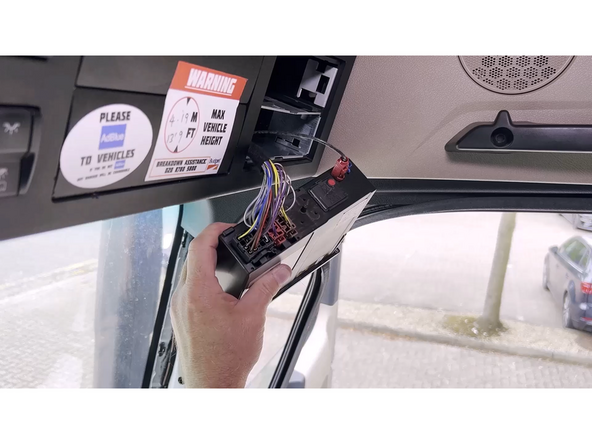
Locate the Thacograph in the cab of the vehicle.
-
Usually it is located above drivers head.
-
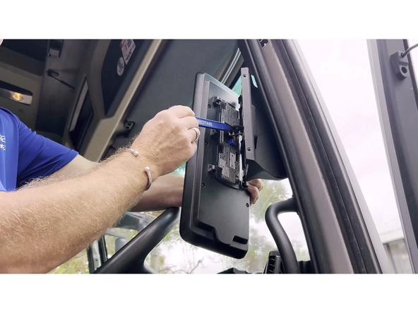
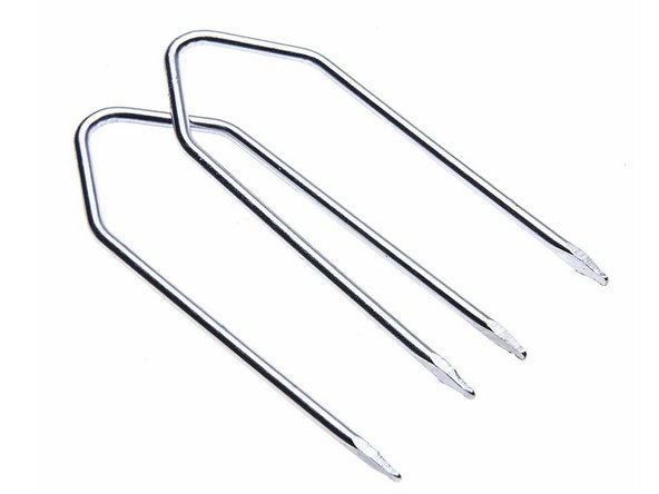
Using the correct tool, remove the tachograph from its mounting location.
-
Pull firmly on both sides at the same time.
-
-
-
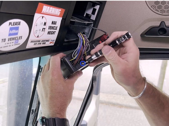
Some tachograph units are protected with a security seal that must be removed to proceed with the installation.
-
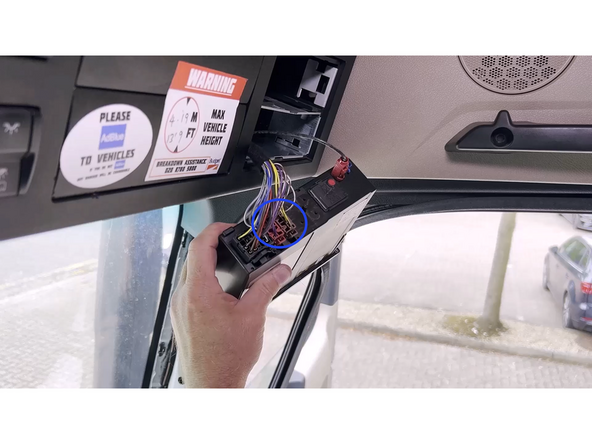
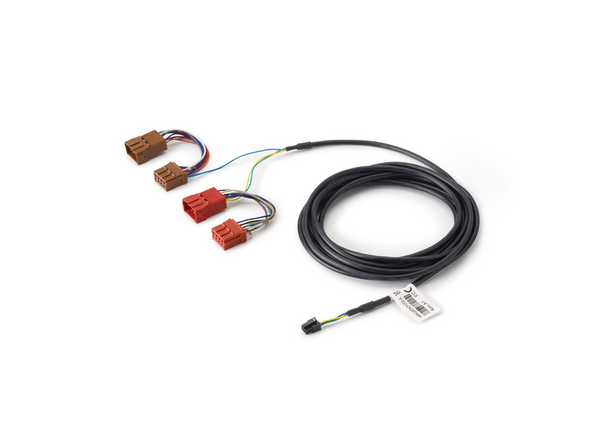
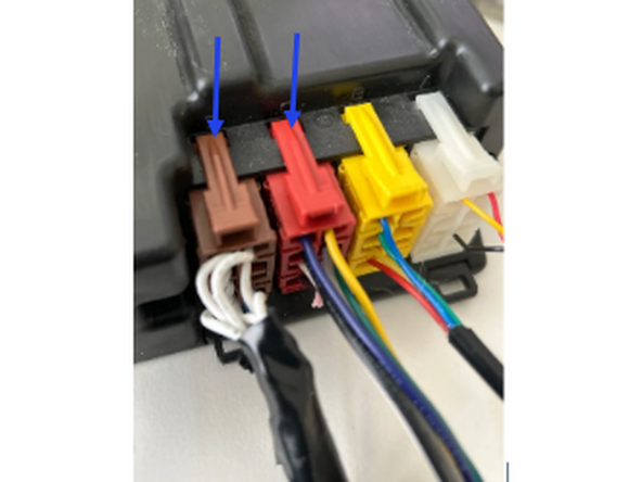
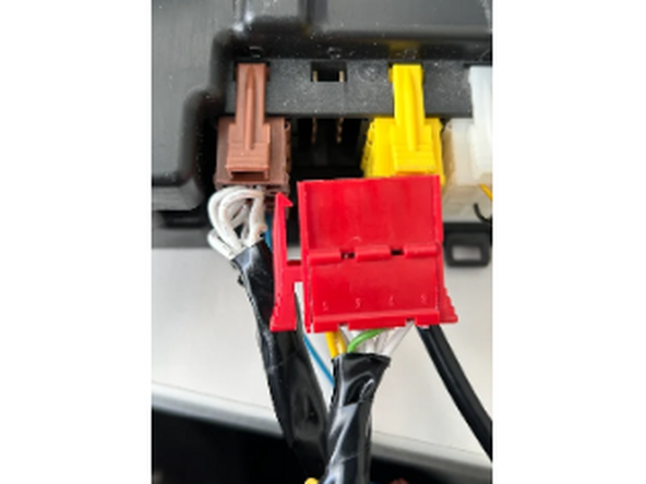
Remove the brown and red connectors.
-
Plug the brown and red tachograph harness connectors into the tachograph until they lock into place.
-
Connect the factory brown and red connectors to the matching female connectors on the tachograph harness. Ensure both connectors are locked into place.
-
-
-
There is multiple possibilities on this step, we will show ONLY the case when port D/Brown connector and C/Red connector are present.
-
If during the installation you find any other configuration, please refer to Tachograph Solution Installation Guide
-
-
-
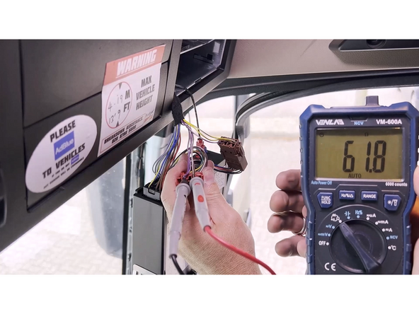
Using a multimeter in ohmmeter mode, measure the CAN termination resistance between pins 5 and 7 of the tachograph’s port C.
-
Ensure the ignition of the vehicle is off.
-
If tachograph port C is already in use and the measured termination resistance is around 60 ohms or less, Cut the pink loop wire.
-
If during the measurement you find any other result, please refer to Tachograph Solution Installation Guide
-
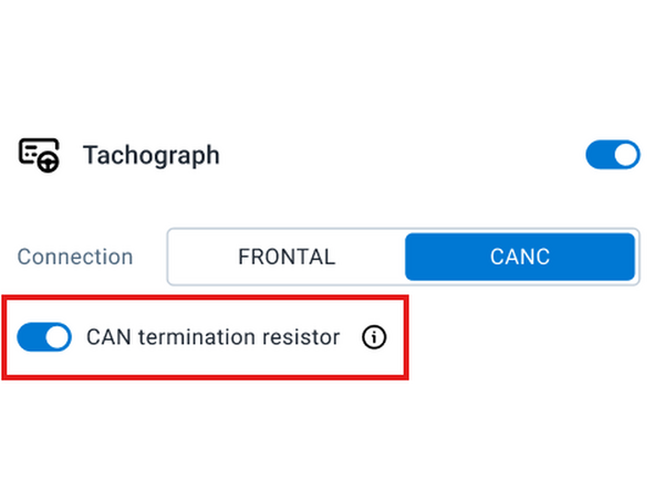
Important: While running MyInstall, make sure you enable the CAN termination resistor toggle
-
-
-
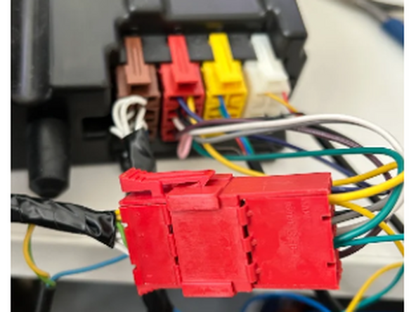
Connect the Red connector on HRN-URTACHO02-A to port C of the tachograph
-
Connect the vehicle’s connector to the other red connector of HRN-URTACHO02-A
-
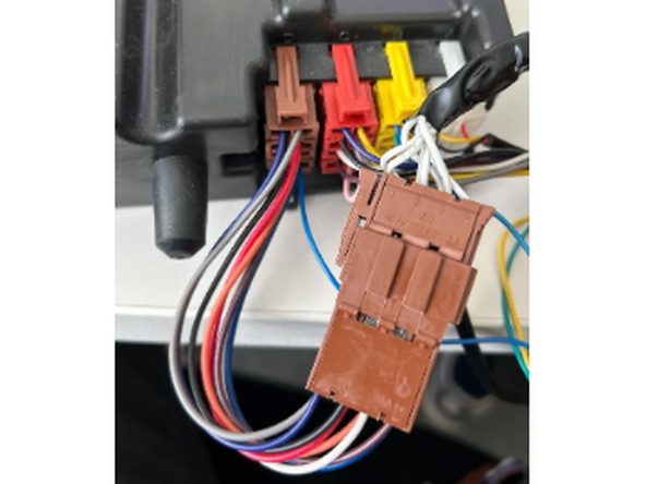
Disconnect the vehicle’s brown connector from port D of the tachograph
-
Connect the vehicle’s connector to the other brown connector on HRN-URTACHO02-A
-
-
-
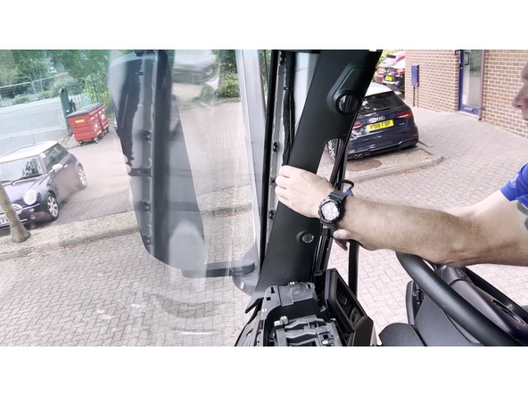
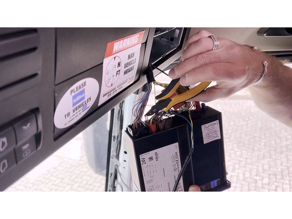
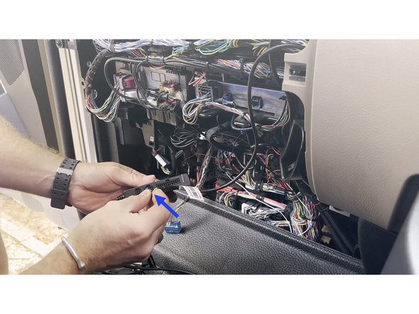
Continue routing the tachograph harness over to the diagnostic port location.
-
Secure all wiring using cable ties.
-
Plug the tachograph harness into the IOX Cold.
-
Ensure it locks into place.
-
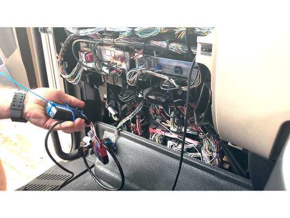
Connect the IOX-COLD to Th Go Device.
-
Secure the connexion with a cable tie.
-
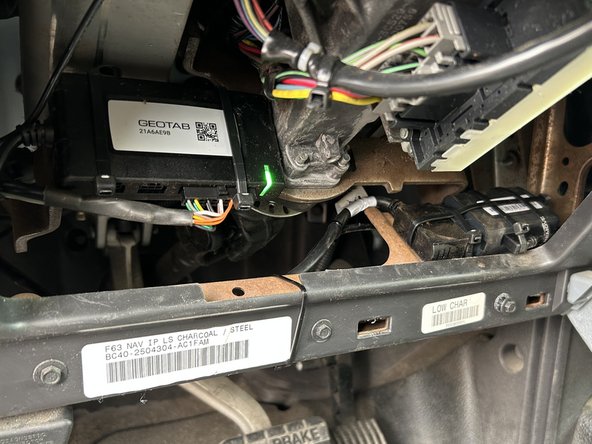
Connect the Go device to the Vehicle.
-
Do not overtighten the cable tie, as this can damage the USB connector.
-
-
-
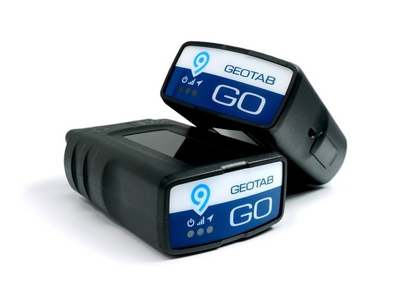
GO device installations for the Cold Chain Solution involve a GO device and a T-harness. Refer to the HRN-GS16K22 Standard 16-Pin T-Harness Kit & HRN-GS09K2 Universal Heavy Duty T-Harness Kit guides for installation instructions.
-
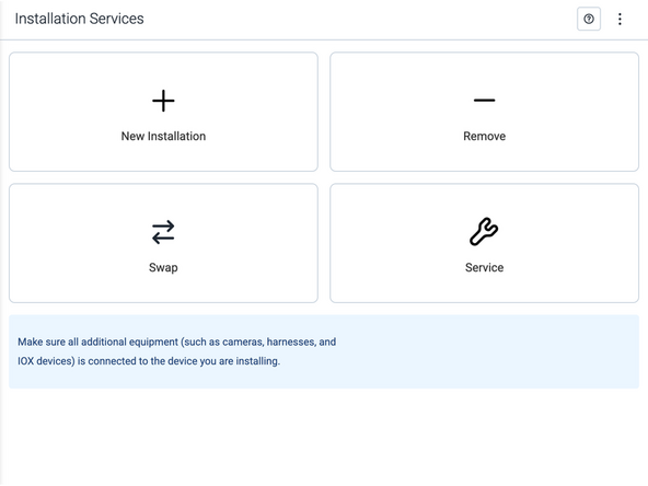
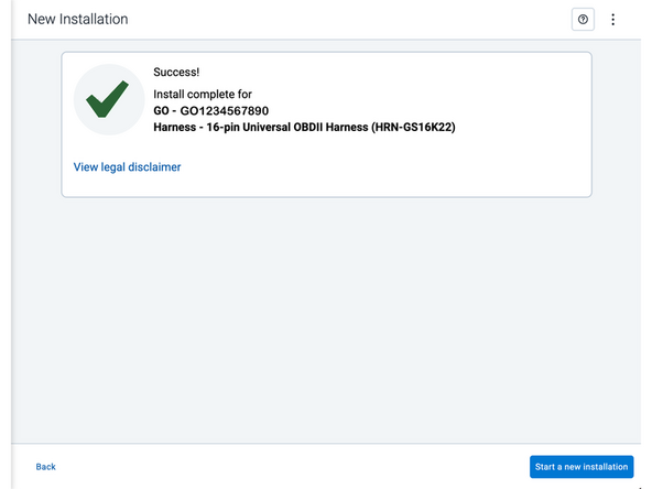
Visit Myinstall to validate the installation and configure the IOX-COLD.
-
In order to configure the IOX COLD you must to login to MyInstall.
-
-
-
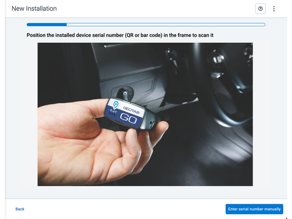
Two options are available to enter the device serial number:
-
Scan the device serial number (QR or barcode) using your mobile device.
-
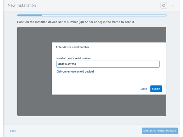
Press Enter serial number manually, enter the serial number, and then press Submit.
-
If you are also removing an old device, press Did you remove an old device? and then enter the removed device serial number.
-
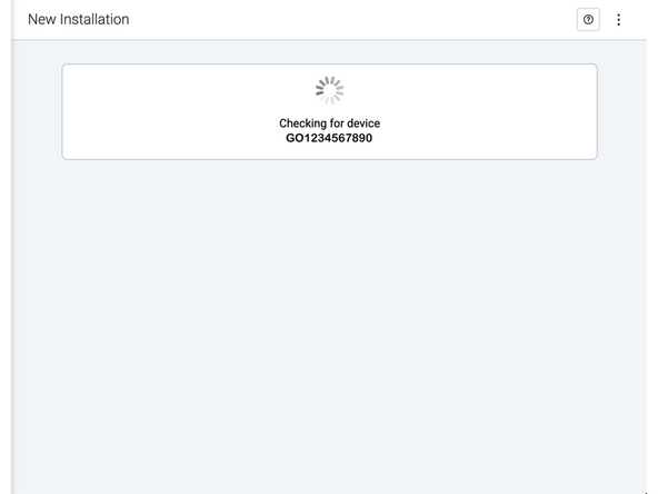
MyInstall takes a moment to check the device status.
-
-
-
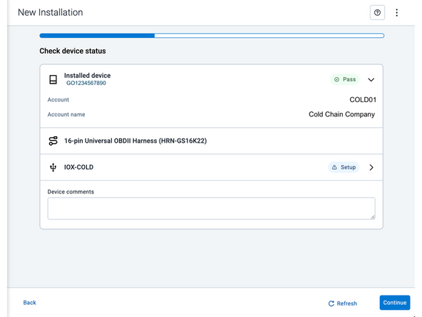
Installed device
-
Pass – The device has successfully communicated with the network in the last 24 hours.
-
Fail – The device has not communicated with the network in the last 24 hours.
-
If the device status shows as FAILED, verify the LED status and turn the ignition / engine off and on again.
-
Press Refresh to check the status again.
-
Refer to the MyInstall User Guide for detailed instructions.
-
-
-
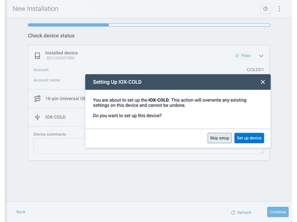
Under Check device status, you will see the connected IOX device.
-
Press Set up device to start.
-
-
-
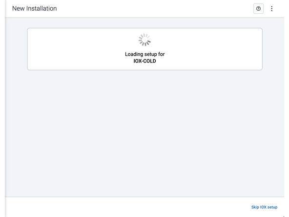
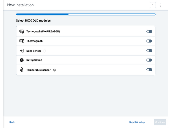
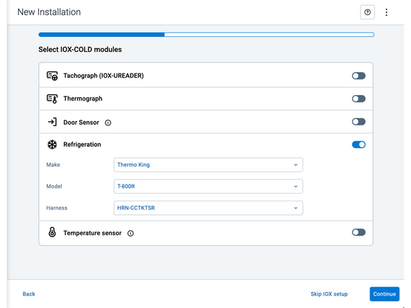
Under Select IOX-COLD modules follow the on-screen instructions to configure and finalize the IOX setup for the installation that you have performed.
-
This may involve configuring settings, or completing any necessary calibration.
-
This image shows an example of what an IOX device setup could look like. The actual screens and options may vary depending on your specific IOX device.
-
After making your selections, press Continue to configure the IOX device.
-
-
-
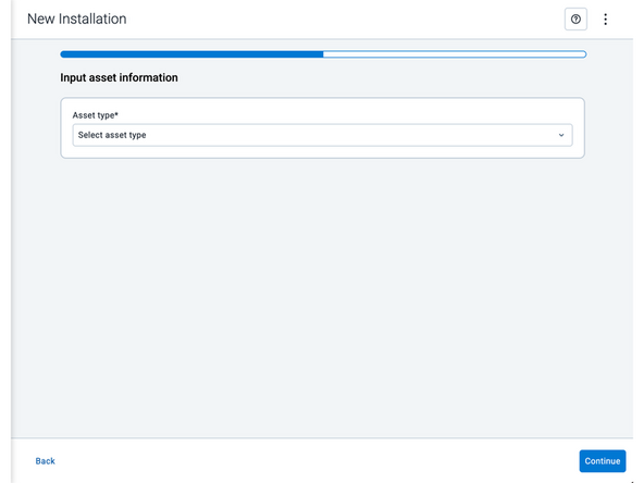
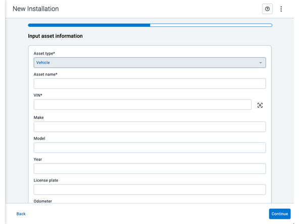
Asset name — Enter the vehicle or asset name. This field is mandatory.
-
VIN — Scan or enter the vehicle identification number (VIN). For scanning, select the scan icon [O] beside the field. This field is mandatory.
-
Make, Model, and Year — This information will be auto populated when you scan or enter a valid VIN. If it is not autopopulated, enter the information manually. NOTE: For some vehicle makes and models, the autopopulate option might not be possible.
-
License plate — Enter the vehicle license plate.
-
Odometer (GO device only) — Enter the vehicle odometer, and select the measurement unit (km or miles).
-
Engine hours (GO device only) — Enter the vehicle engine hours.
-
Camera ID (GO device only) — Scan or enter the installed camera identification (ID) number. NOTE: Depending on the camera type, the camera ID number can also be the camera’s International Mobile Equipment Identity (IMEI), or serial number. Select the information icon ⓘ to learn more about your camera’s ID number.
-
Work order reference — If applicable, enter a work reference number that is associated with the installation.
-
-
-
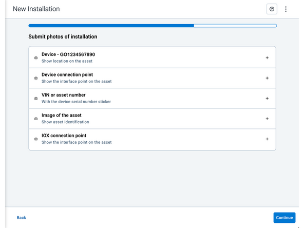
Under Submit photos of installation, upload photos of the service.
-
Press the camera icon to take a photo with your mobile device.
-
Press the plus icon (+) to attach an image from your photo gallery.
-
The number of photos required depends on the device being installed.
-
! IMPORTANT: Ensure that photos do not capture personally identifiable and confidential information.
-