Recommended Tools & Consumables
Hardware & Accessories
-
-
Before starting the installation, ensure the Geotab GO device is unplugged from the vehicle.
-
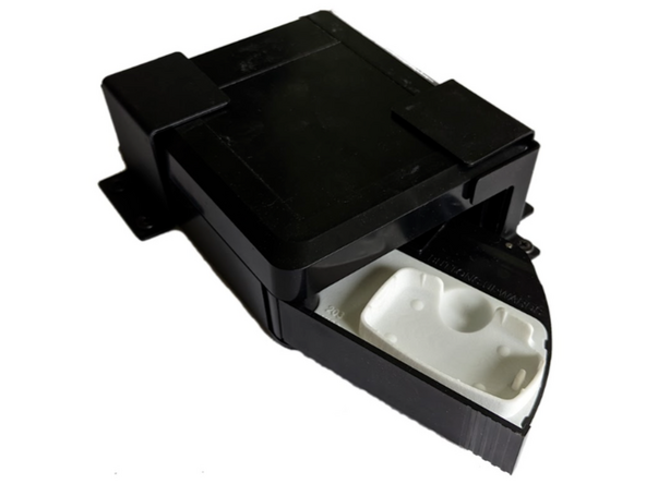
Check that the 3 digit KEYBOX type code found inside the drawer on the white key tray matches the vehicles key fob. Reference photos can be found in the KEYBOX catalog.
-
Physically place the key fob in the white tray and ensure a snug and secure fit, such that the fob easily snaps in place.
-
IOX-KEYBOX is often used in conjunction with IOX-NFCREADERA to control access to the vehicle.
-
-
-
The Key Power Control (KPC) unit is necessary for use on all push-to-start vehicle installations; otherwise the KPC unit is optional.
-
The KPC replaces the key fob battery with power supplied from the IOX-KEYBOX, ensuring it is only powered when required.
-
This accessory aids in preventing the vehicle from being accessed or operated without permission.
-
-
-
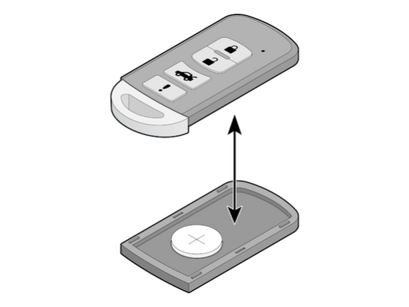
Open the key fob, in accordance with the manufacturer's instructions.
-
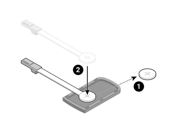
Take note of the battery polarity before removing. Then remove the battery from the key fob.
-
Place the corresponding KPC in the battery position. Ensure the cable will exit the keyfob and pass under the keyfob to the power socket. This prevents the cable from interfering with the IOX-KEYBOX operation.
-
-
-
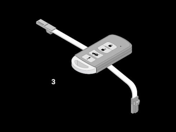
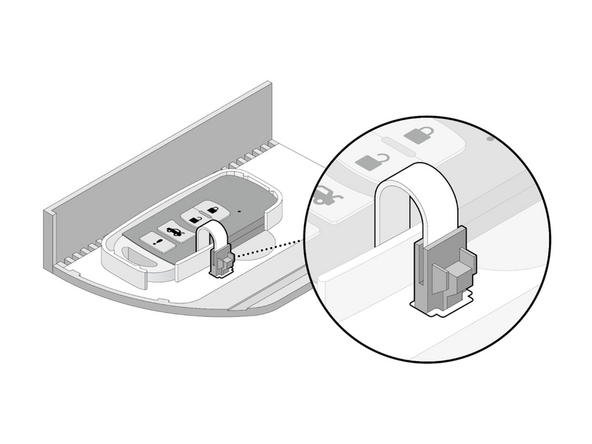
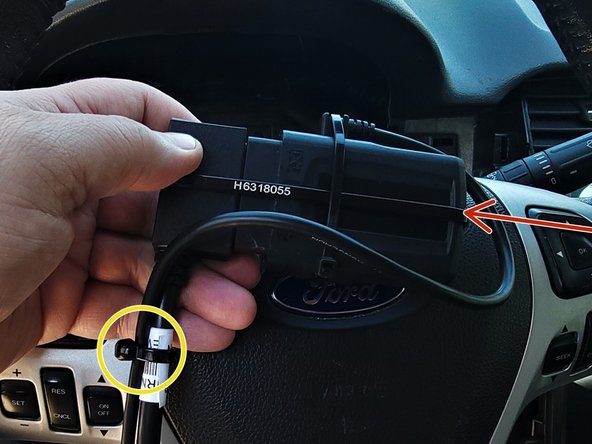
Close the key fob with the cover removed in step 1 and bend the cable in the direction, as seen in the image. Pre-bending of the cable may be required to avoid cable damage. Ensure it is not stretched and contours the fob to minimize strain.
-
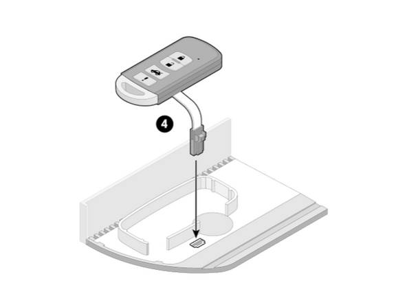
Connect the plug to the socket in the key bed of the box drawer. Ensure the cable exits and passes under the keyfob to the power socket. This prevents excessive cable from interfering with the IOX-KEYBOX operation.
-
Place the key fob in the key bed.
-
Carefully close the drawer of the box, ensuring not to damage any cables.
-
-
-
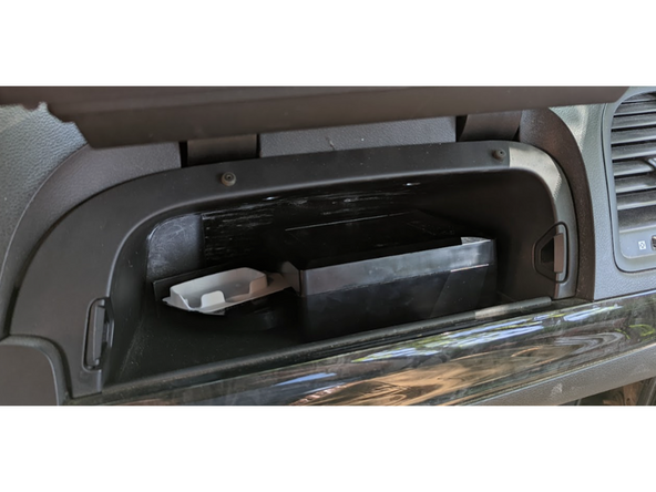
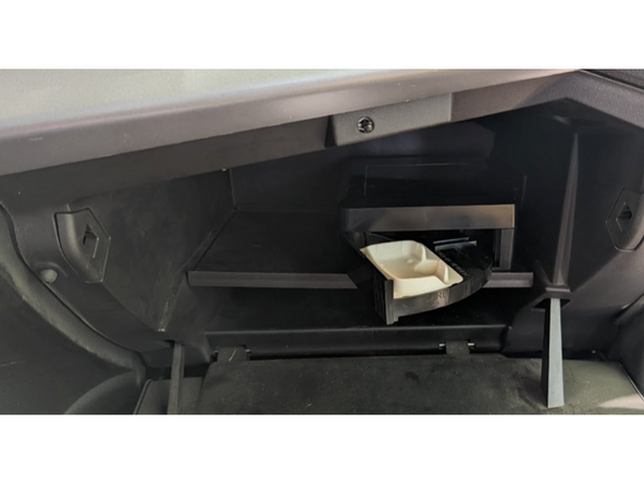
! IMPORTANT: To ensure the key fob remains in place and the unlock/lock commands function reliably, the IOX-KEYBOX should be mounted horizontally. When mounting inside the glove compartment, where the glove compartment floor may tilt when opened or closed. A tilt of 45 degree or less from horizontal through its travel is acceptable.
-
! IMPORTANT: if the glove compartment door needs to be, or will ever be slammed to shut, glove compartment mounting is not recommended.
-
-
-
The IOX-KEYBOX can be installed in a number of locations in the vehicle, depending on its size, configuration, and type. If no modifications can be done to the vehicle, we recommend installing the IOX-KEYBOX in one of the following locations:
-
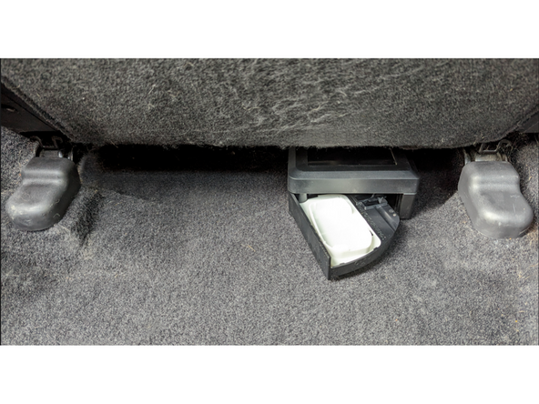
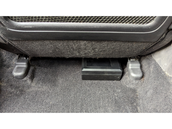
Underneath the driver seat (preferred location)
-
The following alternative mounting locations require additional mounting brackets:
-
In the cargo area.
-
Under the rear vehicle seats.
-
Inside the passenger footwell
-
Inside the glove compartment.
-
-
-
! IMPORTANT: Any additional IOX devices must be installed AFTER the IOX-KEYBOX, and only if the overall daisy chain will not exceed 3.5m, or 3A.
-
WARNING! If the IOX-KEYBOX is installed inside the cabin area/cargo area of a vehicle, it must be contained or otherwise secured to the vehicle to prevent it from becoming a projectile in the event of a collision.
-
Failure to properly secure the IOX-KEYBOX using the recommended brackets could result in serious personal injury and/or vehicle damage.
-
-
-
IOX-KEYBOX is NOT to be installed in the following locations:
-
Where it is exposed to heating sources.
-
Where it is exposed to water (IOX-KEYBOX is rated IP31).
-
Where it is visible from outside the vehicle.
-
Where it can interfere with the safe operation of the vehicle.
-
Where it is not contained within, or physically mounted, or secured to the vehicle.
-
-
-
Prior to installing any equipment, determine a suitable installation location based on the vehicle.
-
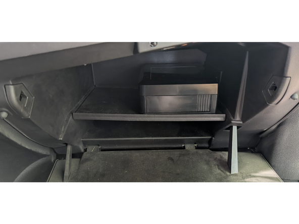
Ensure the IOX-KEYBOX has adequate clearance for the tray to fully open.
-
Determine whether drilling may be required to provide suitable cable routing in glove boxes that are completely enclosed.
-
-
-
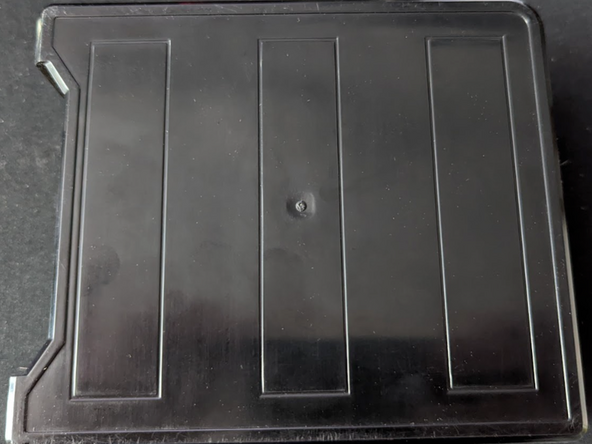
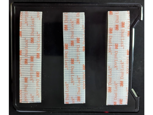
Prepare the IOX-KEYBOX for installation, and attach the provided dual lock adhesive tape to the bottom of the IOX-KEYBOX.
-
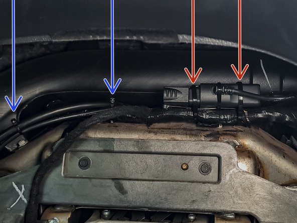
Route the HRN-KEYBOX cable from the IOX-KEYBOX through the access or drilled hole to the location of where the GO device will be installed. Ensure cable routing will not be a safety concern and is concealed within the dash. Secure the cable using cable ties.
-
Using the dual lock, mount the IOX-KEYBOX in the selected location. Ensure the IOX-KEYBOX is mounted securely, and the tray can fully open without obstruction.
-
-
-
Prior to installing any equipment, determine a suitable installation location based on the vehicle.
-
Ensure the IOX-KEYBOX has suitable clearance for the tray to fully open.
-
Consider how the HRN-KEYBOX cable will exit the location and route to the GO device. Avoid high angle bends that may pinch or damage the cable.
-
Ensure there is clearance to properly install the mounting brackets.
-
Mount the IOX-KEYBOX horizontally (flat) and fasten to the vehicle structure.
-
✱ NOTE: When installing in the cargo or under the rear passenger seat areas, additional attachment brackets are required to secure the device.
-
-
-
Select a suitable mounting location that satisfies the mounting requirements for the IOX-KEYBOX.
-
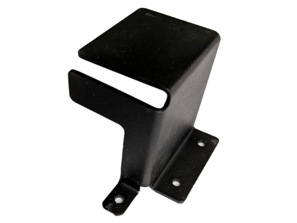
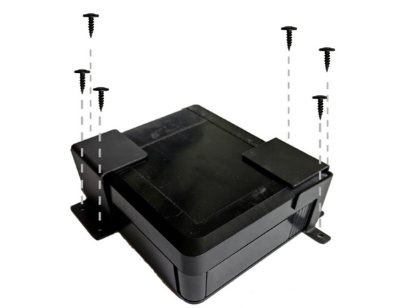
Use the two supplied mounting brackets to securely mount the IOX-KEYBOX under the seat or in the trunk or cargo area. The brackets install diagonally to each other at the corners of the IOX-KEYBOX and are secured with the supplied screws.
-
Ensure the door functions and the brackets restrain the IOX-KEYBOX from movement or removal.
-
-
-
✱ NOTE: When mounting under the passenger seat, ensure you are not directly in front of the hot air duct or heat source.
-
Route the HRN-KEYBOX cable from the IOX-KEYBOX to the location of where the GO device will be installed. Attach the HRN-KEYBOX cable between the T-Harness and GO device, and the IOX connector to the GO IOX port.
-
-
-
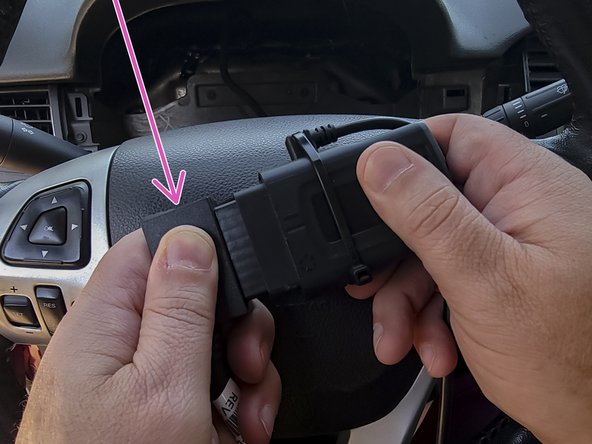
Remove the rubber cover on the GO device to expose the IOX port.
-
Plug the IOX cable into the GO device.
-
Important: you must plug IOX devices into the GO device BEFORE powering up the GO device.
-
-
-
Turn on the vehicle ignition.
-
Verify the LED pattern.
-
The device emits 2 quick beeps every 60 seconds during setup. When setup is complete, all three LEDs turn solid and the device emits 10 quick beeps.
-
-
-
Route the device and harness to the mounting location as needed. The mounting location should have as clear a line of sight to the sky as possible (for cellular/GPS connectivity). Lines of sight through plastics, glass, and composites are generally acceptable.
-
Ensure cable does not interfere with any moving parts.
-
Secure harness as needed with cable ties.
-
Secure the device using 2 cable ties.
-
To ensure reporting quality, the device must be secured with no free movement!
-
Device must NOT be secured such that the bottom side is in direct contact with metal!
-
-
-
All in-vehicle devices and related cabling must be securely fastened and kept clear of all vehicle controls, airbags, and gas, brake and clutch pedals.
-
This requires the use of a cable tie when securing the device or any extension harness to the OBD connector, securing both sides of the harness. If you do not use a cable tie, vibration in the vehicle can lead to a loose connection which could cause the vehicle’s engine computer to fail, causing potential loss of vehicle control and serious injury.
-
Inspect devices and cabling regularly to ensure all devices and cabling continue to be securely attached.
-
If at any point after an in-vehicle device is installed a warning light illuminates on the vehicle dash or the vehicle stalls or has a marked drop in performance, shut off the engine, remove the device, and contact your reseller. Continuing to operate a vehicle with these symptoms can cause loss of vehicle control, and serious injury.
-
-
-
Navigate to one of the following:
-
-
-
Note that the following steps are for the public version of MyInstall.
-
If you have an installer MyAdmin account, use this link
-
This link is also accessible via the MyInstall Public page.
-
-
-
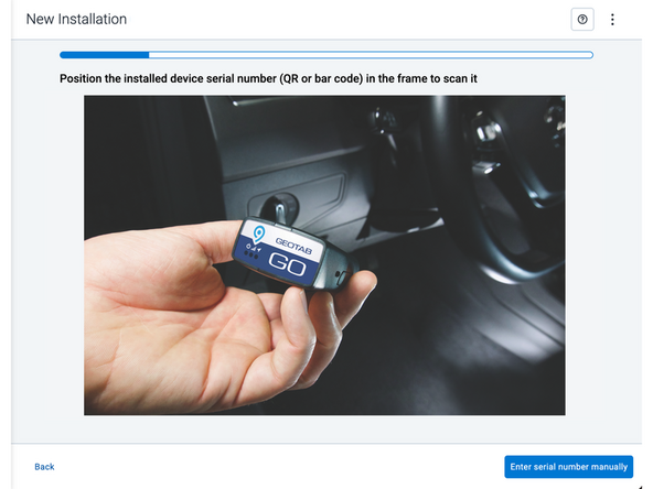
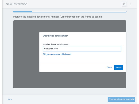
Two options are available to enter the device serial number:
-
Scan the device serial number (QR or barcode) using your mobile device.
-
Press Enter serial number manually, enter the serial number, and then press Submit.
-
If you are also removing an old device, press Did you remove an old device? and then enter the removed device serial number.
-
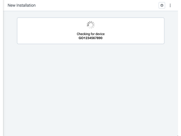
MyInstall takes a moment to check the device status.
-
-
-
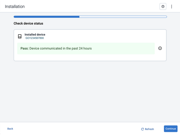
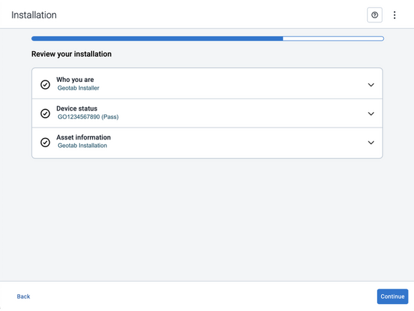
Installed device
-
Pass – The device has successfully communicated with the network in the last 24 hours.
-
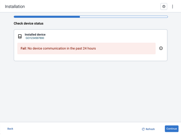
Fail – The device has not communicated with the network in the last 24 hours.
-
If the device status shows as FAILED, verify the LED status and turn the ignition / engine off and on again.
-
Press Refresh to check the status again.
-
Refer to the MyInstall User Guide for detailed instructions.
-
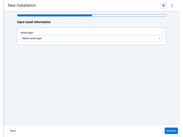
-
-
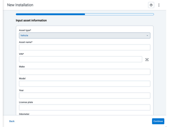
Asset name — Enter the vehicle or asset name. This field is mandatory.
-
VIN — Scan or enter the vehicle identification number (VIN). For scanning, select the scan icon [O] beside the field. This field is mandatory.
-
Make, Model, and Year — This information will be auto populated when you scan or enter a valid VIN. If it is not autopopulated, enter the information manually. NOTE: For some vehicle makes and models, the autopopulate option might not be possible.
-
License plate — Enter the vehicle license plate.
-
Odometer — Enter the vehicle odometer, and select the measurement unit (km or miles).
-
Engine hours — Enter the vehicle engine hours.
-
Camera ID (GO device only) — Scan or enter the installed camera identification (ID) number. NOTE: Depending on the camera type, the camera ID number can also be the camera’s International Mobile Equipment Identity (IMEI), or serial number. Select the information icon ⓘ to learn more about your camera’s ID number.
-
Work order reference — If applicable, enter a work reference number that is associated with the installation.
-
-
-
For the latest version of the Limitations of Use
-
Your in-vehicle devices must be kept clear of debris, water and other environmental contaminants. Failure to do so may result in units malfunctioning or short-circuiting, which can lead to a fire hazard and cause loss or serious injury.
-
This product does not contain any user-serviceable parts. Configuration, servicing, and repairs must only be made by an authorized reseller or installer. Unauthorized servicing of these products will void your product warranty.
-
The simplified EU declaration of conformity referred to in Article 10(9) shall be provided as follows:
-
Hereby, Geotab (Address: 2440 Winston Park Drive, Oakville, Ontario L6H 7V2, Canada, Phone number: 1 (877) 436-8221) declares that the radio equipment type ‘telematics device’ is in compliance with Directive 2014/53/EU. The full text of the EU declaration of conformity is available here.
-
WARNING: Cancer and Reproductive Harm
-