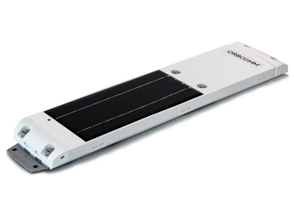
v1.3

Minor Versionm

by Alkesh Dhak

    • NOTE: Professional Installation Required — Installation of the ORBCOMM Asset Tracker requires the installer to have sufficient technical knowledge and expertise for mobile device installation and integration into modern vehicles/assets

    • Some installations are not straight forward and must be completed by an Authorized Installer to ensure a secure installation.

    • An unsecure device installation can cause poor electric and/or data connection that can lead to short circuits and fires or cause malfunctions.

  1. The ORBCOMM kit contents are shown here. Ensure all items are included.
    • The ORBCOMM kit contents are shown here. Ensure all items are included.

  2. Begin by activating the asset tracker, removing the red label, and verifying LED activity. Once the LED turns solid blue followed by solid green, the unit is ready for installation. Begin by activating the asset tracker, removing the red label, and verifying LED activity. Once the LED turns solid blue followed by solid green, the unit is ready for installation. Begin by activating the asset tracker, removing the red label, and verifying LED activity. Once the LED turns solid blue followed by solid green, the unit is ready for installation.
    • Begin by activating the asset tracker, removing the red label, and verifying LED activity. Once the LED turns solid blue followed by solid green, the unit is ready for installation.

  3. Make note of the device serial number and asset IMEI number for future reference, either by taking a picture or writing the numbers down.
    • Make note of the device serial number and asset IMEI number for future reference, either by taking a picture or writing the numbers down.

  4. Remove the two 11/32" lock nuts and device harness cover. Set the lock nuts aside for now, as they will need to be reinstalled later. Remove the sealing cap connector.
    • Remove the two 11/32" lock nuts and device harness cover. Set the lock nuts aside for now, as they will need to be reinstalled later.

    • Remove the sealing cap connector.

  5. Find a suitable location on the trailer to mount the device.
    • Find a suitable location on the trailer to mount the device.

    • To reduce likelihood of vandalism, mount the device as high as possible above the nose box. Use your ladder.

    • Before drilling any holes, verify that there are no obstructions inside the trailer, make sure you have access to the interior panel, and obtain approval from the Fleet Manager.

  6. Use the provided alcohol pad to clean any dirt or grease from the mounting area on the asset, and then use the scour pad. DO NOT scour beyond the the asset tracker's mounting area. Next, clean the points using the alcohol pads and then prime the points using the 3M adhesive primer.
    • Use the provided alcohol pad to clean any dirt or grease from the mounting area on the asset, and then use the scour pad. DO NOT scour beyond the the asset tracker's mounting area.

    • Next, clean the points using the alcohol pads and then prime the points using the 3M adhesive primer.

    • Make sure that the primer is dry before mounting the device!

  7. Remove all four VHB tape liners from the device.
    • Remove all four VHB tape liners from the device.

  8. Align the device brackets with the previously drilled holes and press firmly for at least 60 seconds.
    • Align the device brackets with the previously drilled holes and press firmly for at least 60 seconds.

  9. Secure the device using the blind rivet and an appropriate rivet gun.
    • Secure the device using the blind rivet and an appropriate rivet gun.

    • A hand pop rivet gun will not work - DO NOT ATTEMPT! While a heavy duty hand riveter will work, an electric or pneumatic rivet gun/tool is recommended.

  10. Reinstall the harness connector that was removed earlier and apply the supplied dielectric grease into the female contacts of the connector. Next, plug the harness into the device and put the cover back on.
    • Reinstall the harness connector that was removed earlier and apply the supplied dielectric grease into the female contacts of the connector.

    • Next, plug the harness into the device and put the cover back on.

  11. Secure the harness to the device using a cable tie.
    • Secure the harness to the device using a cable tie.

  12. Drill a hole for the harness to pass through and install a grommet in the hole. A hole location directly in line with the nose box makes for easier routing and may even be retrievable from the nose box without removing the interior access panel. Align the harness with the passthrough hole and secure it using the included P-clamps and screws.
    • Drill a hole for the harness to pass through and install a grommet in the hole.

    • A hole location directly in line with the nose box makes for easier routing and may even be retrievable from the nose box without removing the interior access panel.

    • Align the harness with the passthrough hole and secure it using the included P-clamps and screws.

  13. Pass the entire length of the harness through the trailer wall and seal any holes using a silicone sealant.
    • Pass the entire length of the harness through the trailer wall and seal any holes using a silicone sealant.

  14. Remove the bolts that secure the nose box connector plate to the housing and then carefully pull the nose box connector plate away from the housing. Remove the bolts that secure the nose box connector plate to the housing and then carefully pull the nose box connector plate away from the housing.
    • Remove the bolts that secure the nose box connector plate to the housing and then carefully pull the nose box connector plate away from the housing.

  15. In this example, the device harness is not directly accessible through the nose box passthrough hole. Depending on your trailer type, you might need to remove the lower access panel as shown.
    • In this example, the device harness is not directly accessible through the nose box passthrough hole.

    • Depending on your trailer type, you might need to remove the lower access panel as shown.

  16. Once the panel has been removed, retrieve the harness from the wall cavity and then route the harness through the nose box passthrough. Once the panel has been removed, retrieve the harness from the wall cavity and then route the harness through the nose box passthrough.
    • Once the panel has been removed, retrieve the harness from the wall cavity and then route the harness through the nose box passthrough.

  17. Install fuse holders on the blue and brown wires, and then install the ring connector on the black wire. Install fuse holders on the blue and brown wires, and then install the ring connector on the black wire.
    • Install fuse holders on the blue and brown wires, and then install the ring connector on the black wire.

  18. You will need to connect the device to the J560 connector in the nose box. Refer to the J560 diagram to determine the correct connection. You will need to connect the device to the J560 connector in the nose box. Refer to the J560 diagram to determine the correct connection.
    • You will need to connect the device to the J560 connector in the nose box. Refer to the J560 diagram to determine the correct connection.

  19. Secure any excess wiring and then reassemble the nose box.
    • Secure any excess wiring and then reassemble the nose box.

  20. Reinstall any access panels you had to remove.
    • Reinstall any access panels you had to remove.

  21. The installation is now completed!
    • The installation is now completed!

Finish Line

Attached Documents

Ezequiel Montalvo

Member since: 09/08/2022

12 Guides authored

Team

Field Service Specialists Member of Field Service Specialists

8 Members

95 Guides authored