-
-
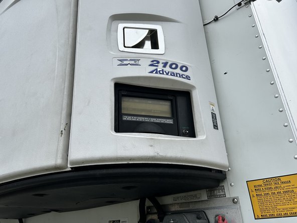
Open and access the left, right and/or center compartments of the refrigeration unit. Ideally, the GO RUGGED & IOX-COLD RUGGED should be mounted close to the location of the refrigeration unit controller and its START / RUN switch.
-
In some cases, you may need to mount the GO RUGGED & IOX-COLD RUGGED in a location that is on the opposite side of the refrigeration unit controller and its START / RUN switch. Note that the mounting location must be within three meters of the connection points (communication harness and power, ground, and ignition).
-
Identify the mounting location of the GO RUGGED & IOX-COLD RUGGED. The location must be a solid part of the vehicle.
-
Ensure the device has a good line of sight to the sky.
-
-
-
The GO RUGGED harness can be positioned out the back of the device for through-hole mounting, or it can be positioned to exit the side of the device.
-
To route the harness out of the side, remove the plastic cover to reposition the harness.
-
If the installation requires you to pass the GO RUGGED harness out of the back of the device for through-hole mounting, refer to the instructions in the GO RUGGED guide.
-
-
-
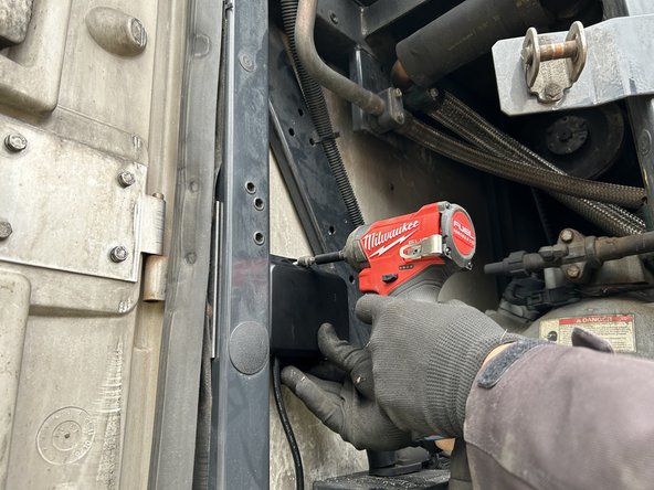
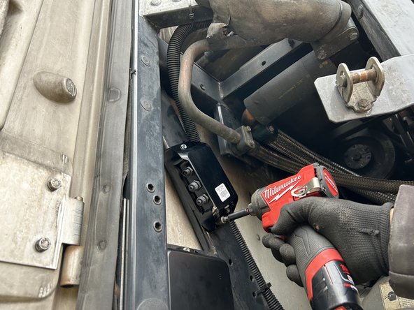
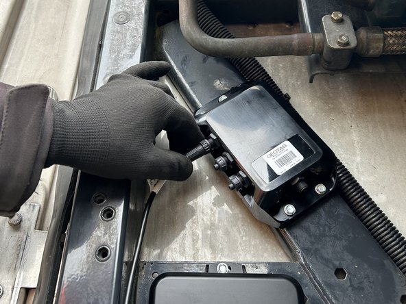
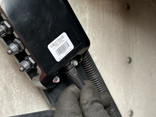
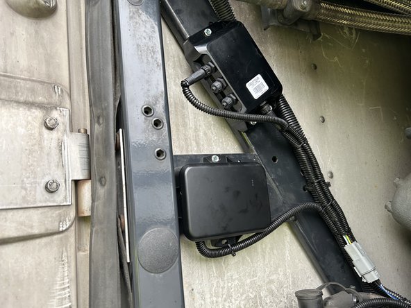
Mount the GO RUGGED and the IOX-COLD RUGGED devices using the screws included in the kit.
-
Use extreme caution when drilling holes in the refrigeration unit. Before drilling, check behind the mounting location to ensure the area is clear of any obstructions or electrical wires/components. Drilling into electrical wiring or refrigerant lines poses a fire risk.
-
Do not mount the devices close to any heat sources, and ensure that the mounting area does not interfere with any other components. Ideal mounting locations may vary by trailer type.
-
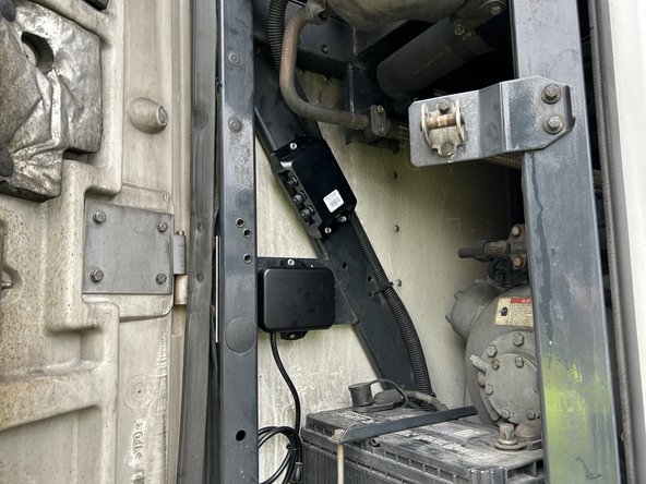
It is highly recommended to orient the IOX-COLD RUGGED such that its connectors face downwards. Installing the device this way prevents water retention near the connectors and mitigates any potential issue of water ingress within the box in the event of a breach.
-
-
-
Refer to the guides in the Refrigeration Unit category for instructions specific to the refrigeration unit you are working on.
-
-
-
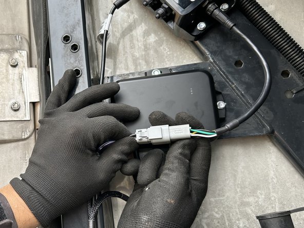
Connect the HRN-HBRPIOXEXT harness to the 4-pin jack on the side of the IOX-COLD RUGGED.
-
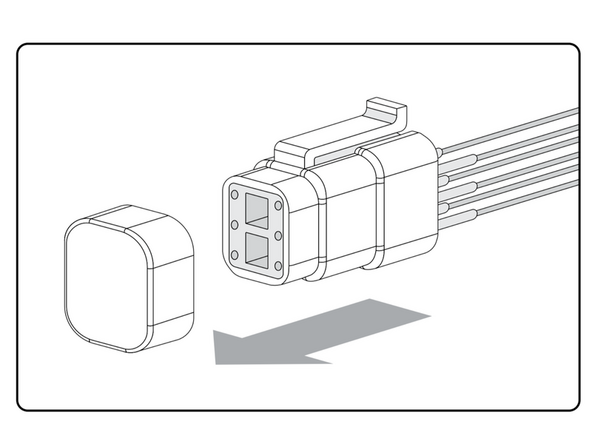
Remove the cap from the male 6-pin GO RUGGED amphenol connector.
-
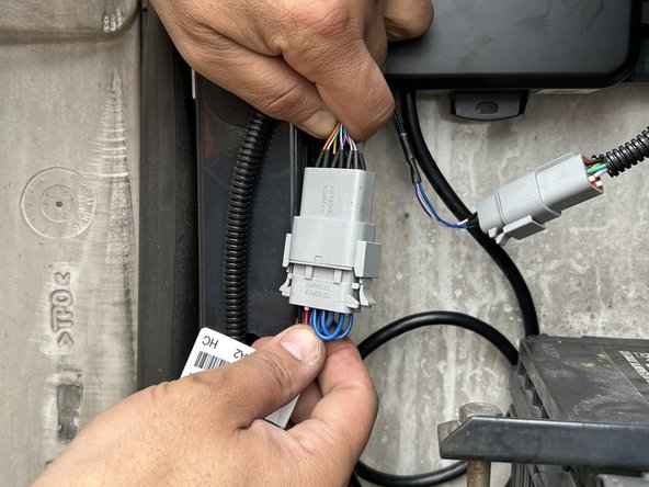
Connect the male 6-pin GO RUGGED connector to the female 6-pin socket on the HRN-HBRPIOXEXT harness.
-
Ensure the connection is secure and locked into place.
-
Use dielectric grease whenever connections may be exposed to moisture.
-
-
-
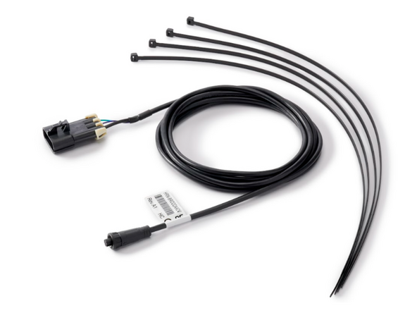
Connect the HRN-RW03K4 harness to the GO RUGGED.
-
Ensure the connection is secure and locked into place.
-
Use dielectric grease whenever connections may be exposed to moisture.
-
-
-
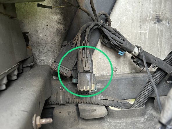
Identify the connection points for Power, Ignition & Ground.
-
Refer to the information in the Cold Chain Trailers Power and Ignition Location Guide.
-
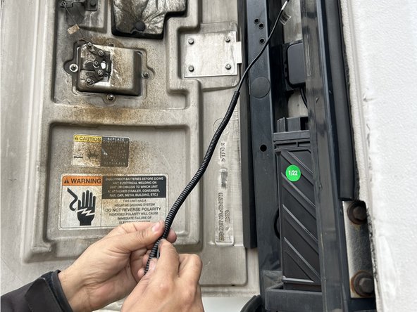
In some cases, you may need to extend the wires to reach the connection point.
-
Ensure you use wire loom to protect the wires when routing through the engine compartment.
-
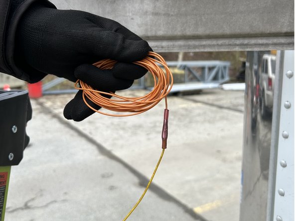
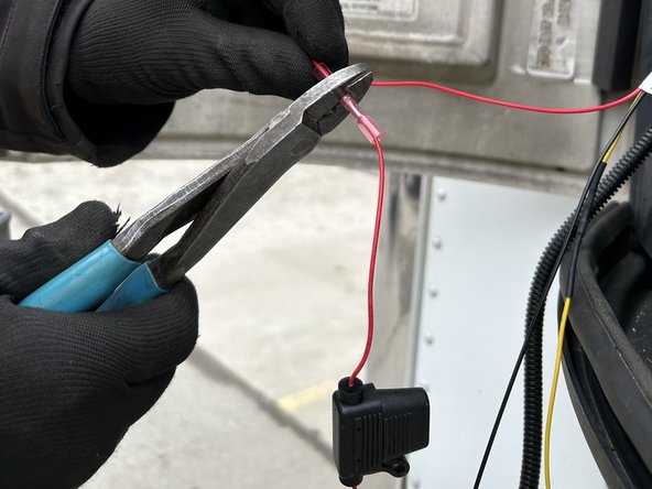
Prepare the harness by attaching fuse holders to the Power (Red) and Ignition (Yellow) wires using the contents provided in the HRN-5AFUSEKIT.
-
The fuse holders should be located within 6 inches of the refrigeration unit's main power and ignition connection points.
-
Use a heat gun or other heat source to heat shrink the butt splice connectors.
-
-
-
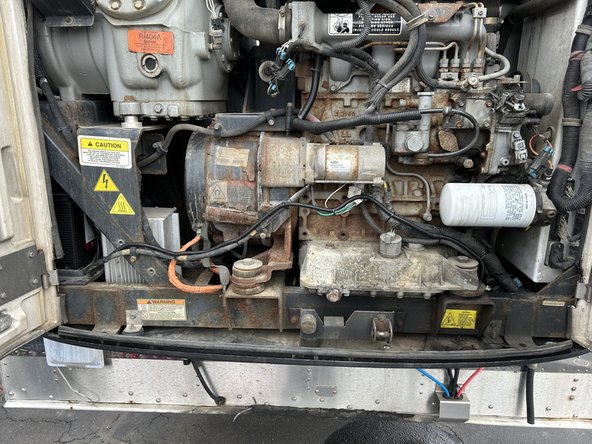
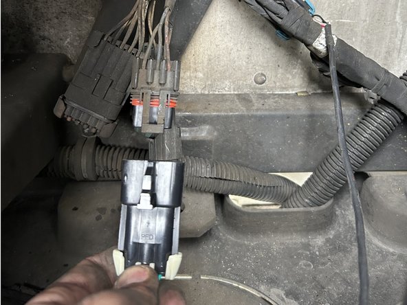
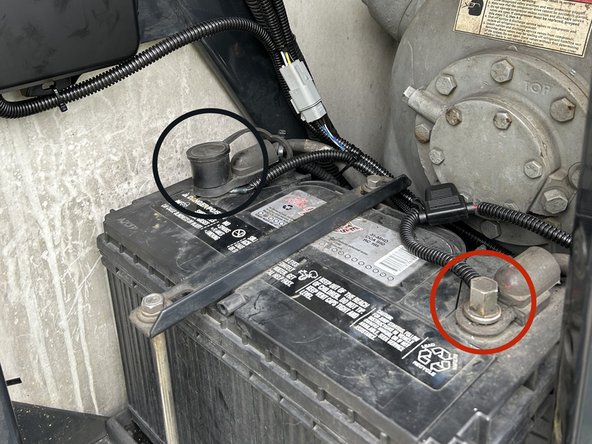
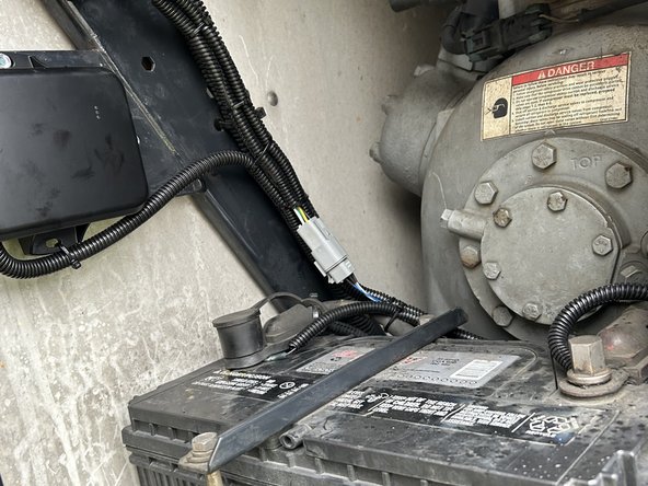
In this example installation, we connect directly to the battery of the refrigeration unit for our constant power and ground connections.
-
Some Cold Chain harnesses already contain a three-wire harness branch that can be directly connected to the GO RUGGED's HRN-RW03K4 three-wire harness. In these cases, make sure to refer to the Refrigeration Unit guides in the Cold Chain category for instructions specific to the refrigeration unit you are working on.
-
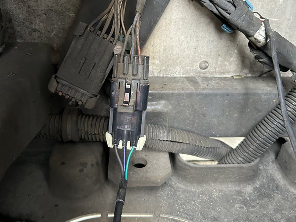
RED Battery Wire - Locate and verify a constant +12/24V Battery source.
-
BLACK Ground Wire - Locate and verify a ground source. The reference point directly comes from the battery terminal, and the refrigeration units chassis.
-
Always use a digital multimeter to locate and verify your connection points.
-
-
-
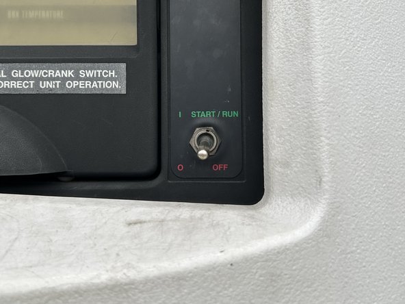
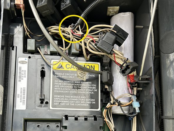
YELLOW Ignition Wire - The ignition wire must be connected to the refrigeration unit controller ignition source.
-
Verify that the ignition interface point has 12V/24V when the refrigeration unit's START / RUN switch is ON.
-
Verify that the ignition interface point has 0V when the refrigeration unit’s START / RUN switch is OFF.
-
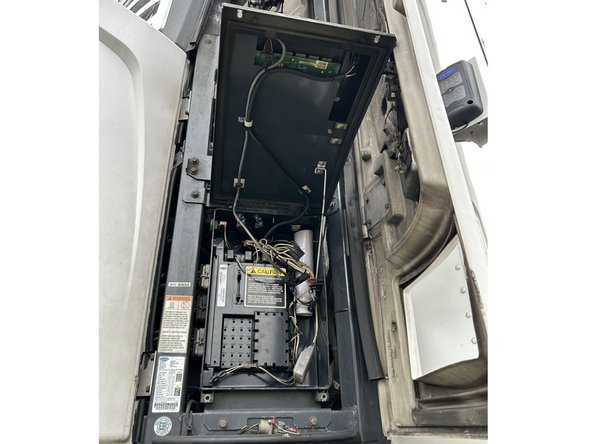
You may need to open the controller panel to access the wires for your ignition source.
-