Introduction
This guide describes how to install a IOX-COLD RUGGED & GO RUGGED device using the HRN-RW03K4 harness into a trailer with a refrigeration unit.
Recommended Tools & Consumables
Hardware & Accessories
-
-
Some installations are not straightforward and must be completed by an Authorized Installer to ensure a secure installation.
-
Installation of the IOX-COLD RUGGED requires the installer to have sufficient technical knowledge and expertise for mobile device installation and integration into modern vehicles, such as a certified Geotab® Installer certification or equivalent.
-
Situations that may require professional installation from an Authorized Installer include the following:
-
Vehicle mounting modifications are required to secure the device, such as: removing panels, drilling, opening and accessing the right and/or center compartments of the refrigeration unit (depending on the location of the controller and its START / RUN switch).
-
The device does not beep six times and power on when first installed.
-
The installer questions their ability to complete a secure installation according to these instructions.
-
Do not attempt to install, reconfigure or remove any product from a vehicle while the vehicle is in motion or otherwise in operation. All installations, configurations, or removals must be done only in stationary vehicles that are securely parked.
-
Attempting to service devices while the vehicle is in motion could result in malfunctions or accidents, leading to death or serious personal injury.
-
-
-
The GO RUGGED device must be disconnected from the vehicle prior to installation. Additionally, you must read and follow all instructions and warnings to prevent serious injury and/or vehicle damage.
-
Before installing the GO RUGGED & IOX-COLD RUGGED, read and follow the device installation instructions, and read and follow the important safety information and limitations of use section at the end of this document. Always read and follow all safety information to prevent loss of vehicle control and serious injury.
-
All IOX-COLD RUGGED and GO RUGGED cabling must be securely fastened and routed clear of hot surfaces, vehicle controls, and moving components in the engine or refrigeration unit. Failure to do so may result in damaged components, refrigeration unit malfunction, or collisions leading to death or serious personal injury.
-
All powered connections must be fitted with overcurrent limit protection. Geotab offers the HRN-5AFUSKIT, which helps minimize configuration complexity, reduces installation time, and improves reliability.
-
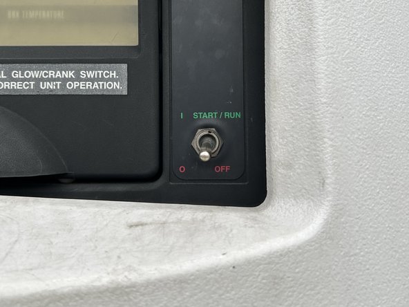
Turn off the vehicle's engine and the microprocessor's START / RUN switch before installation. Failure to do so may result in unintended motor activation, sudden vehicle shutdown, erratic vehicle behavior, component/accessory damage, or pose an electrical hazard leading to death or serious injury.
-
You must finalize the installation by using the Geotab installation tool. The tool applies the proper configuration to the IOX-COLD RUGGED to ensure data is transmitted correctly.
-
-
-
To ensure proper communication with the device, the GO RUGGED device must be assigned to the customer’s database BEFORE installation.
-
Before installing the device, take note of the following information. You will need this information to request support and to activate the device:
-
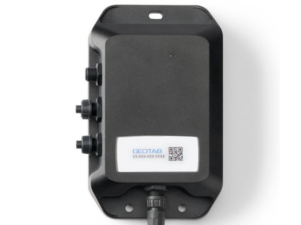
GO RUGGED device serial number
-
Found above barcode on the device label at the bottom of the GO RUGGED device.
-
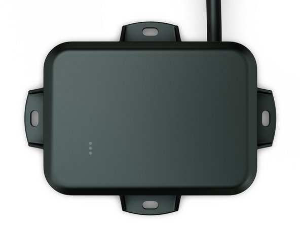
IOX-COLD RUGGED device serial number
-
Found on the device label on the top of the device.
-
Fleet Alias / Number / ID
-
License Plate, VIN, year, and make & model of engine and vehicle chassis
-
-
-
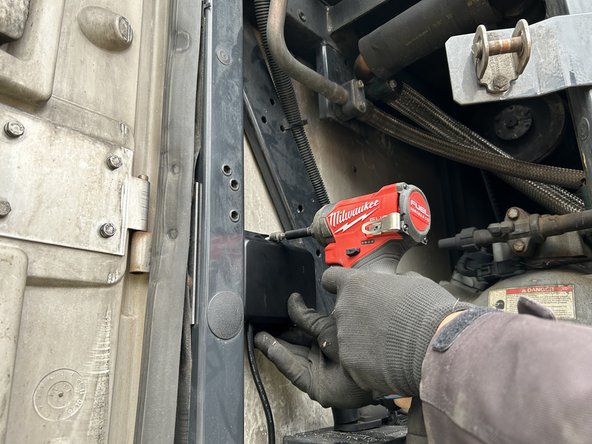
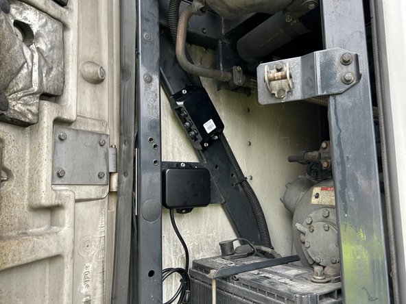
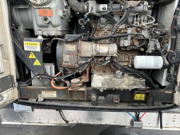
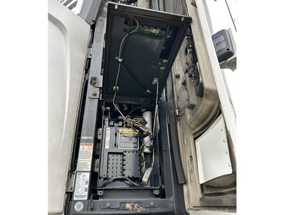
Open and access the left, right and/or center compartments of the refrigeration unit. Ideally, the GO RUGGED & IOX-COLD RUGGED should be mounted close to the location of the refrigeration unit controller and its START / RUN switch.
-
In some cases, you may need to mount the GO RUGGED & IOX-COLD RUGGED in a location that is on the opposite side of the refrigeration unit controller and its START / RUN switch. Note that the mounting location must be within three meters of the connection points (communication harness and power, ground, and ignition).
-
Identify the mounting location of the GO RUGGED & IOX-COLD RUGGED. The location must be a solid part of the vehicle.
-
Ensure the device has a good line of sight to the sky.
-
-
-
The GO RUGGED harness can be positioned out the back of the device for through-hole mounting, or it can be positioned to exit the side of the device.
-
To route the harness out of the side, remove the plastic cover to reposition the harness.
-
If the installation requires you to pass the GO RUGGED harness out of the back of the device for through-hole mounting, refer to the instructions in the GO RUGGED guide.
-
-
-
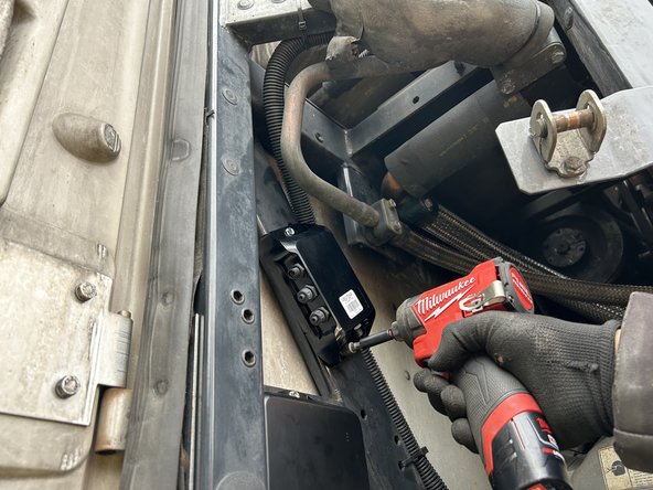
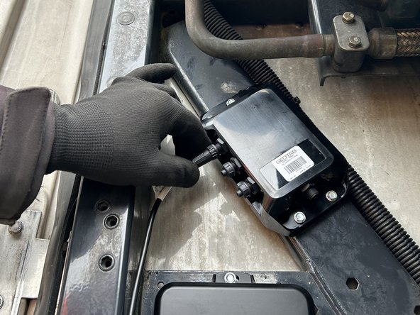
Mount the GO RUGGED and the IOX-COLD RUGGED devices using the screws included in the kit.
-
Use extreme caution when drilling holes in the refrigeration unit. Before drilling, check behind the mounting location to ensure the area is clear of any obstructions or electrical wires/components. Drilling into electrical wiring or refrigerant lines poses a fire risk.
-
Do not mount the devices close to any heat sources, and ensure that the mounting area does not interfere with any other components. Ideal mounting locations may vary by trailer type.
-
It is highly recommended to orient the IOX-COLD RUGGED such that its connectors face downwards. Installing the device this way prevents water retention near the connectors and mitigates any potential issue of water ingress within the box in the event of a breach.
-
-
-
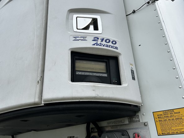
Refer to the guides in the Refrigeration Unit category for instructions specific to the refrigeration unit you are working on.
-
-
-
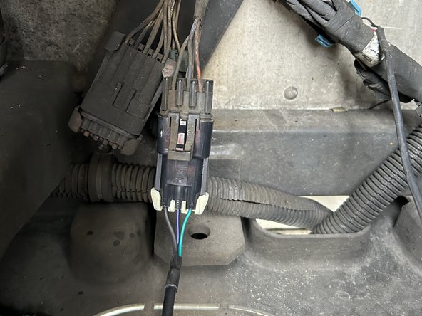
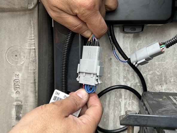
Connect the HRN-HBRPIOXEXT harness to the 4-pin jack on the side of the IOX-COLD RUGGED.
-
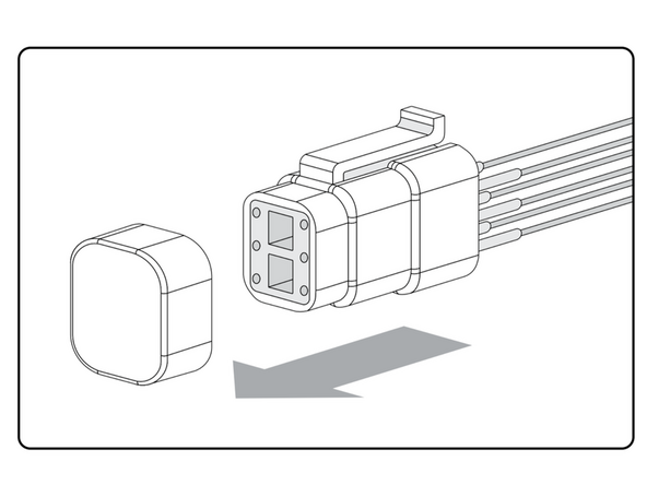
Remove the cap from the male 6-pin GO RUGGED amphenol connector.
-
Connect the male 6-pin GO RUGGED connector to the female 6-pin socket on the HRN-HBRPIOXEXT harness.
-
Ensure the connection is secure and locked into place.
-
Use dielectric grease whenever connections may be exposed to moisture.
-
-
-
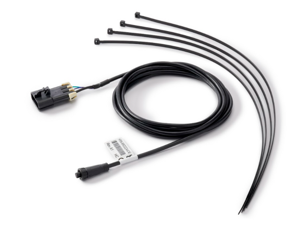
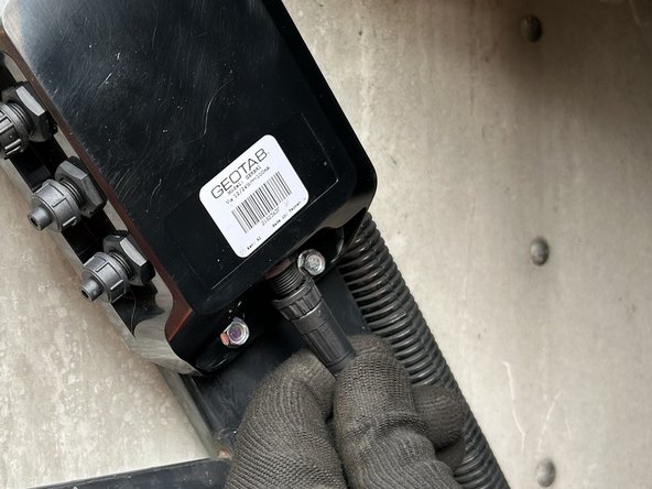
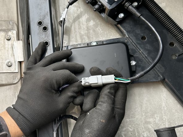
Connect the HRN-RW03K4 harness to the GO RUGGED.
-
Ensure the connection is secure and locked into place.
-
Use dielectric grease whenever connections may be exposed to moisture.
-
-
-
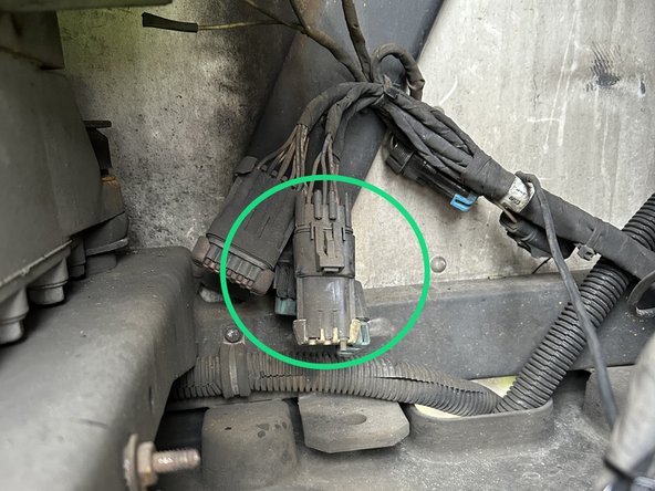
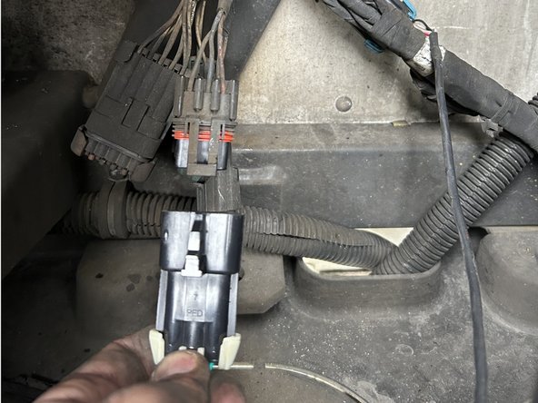
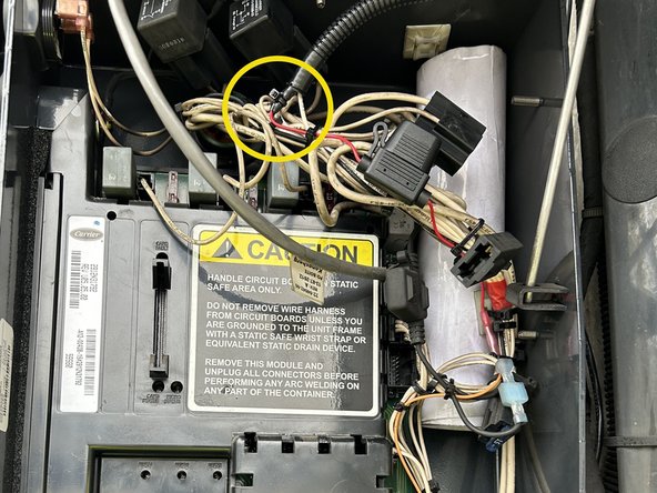
Identify the connection points for Power, Ignition & Ground.
-
Refer to the information in the Cold Chain Trailers Power and Ignition Location Guide.
-
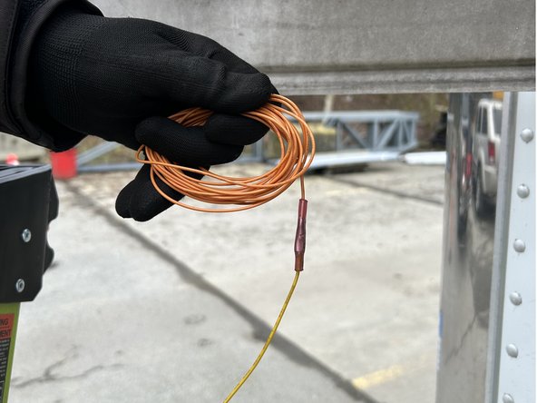
In some cases, you may need to extend the wires to reach the connection point.
-
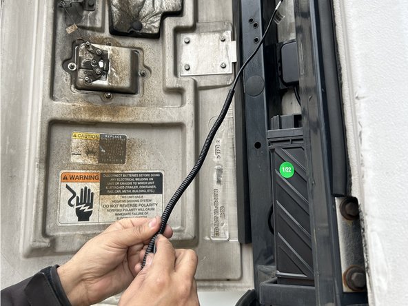
Ensure you use wire loom to protect the wires when routing through the engine compartment.
-
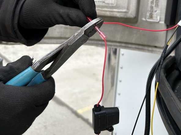
Prepare the harness by attaching fuse holders to the Power (Red) and Ignition (Yellow) wires using the contents provided in the HRN-5AFUSEKIT.
-
The fuse holders should be located within 6 inches of the refrigeration unit's main power and ignition connection points.
-
Use a heat gun or other heat source to heat shrink the butt splice connectors.
-
-
-
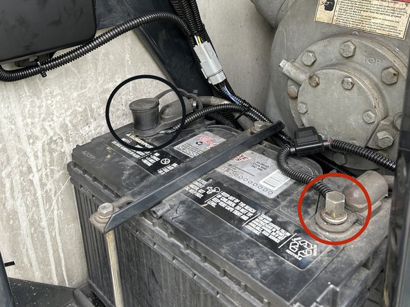
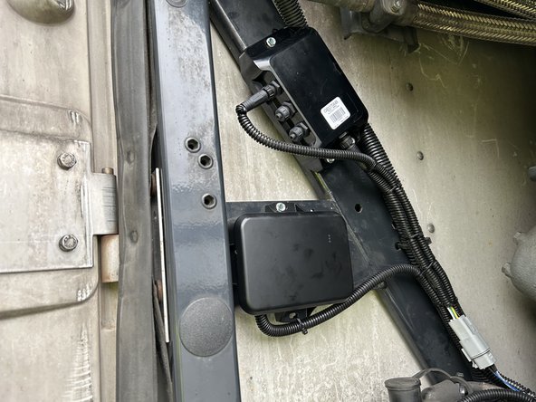
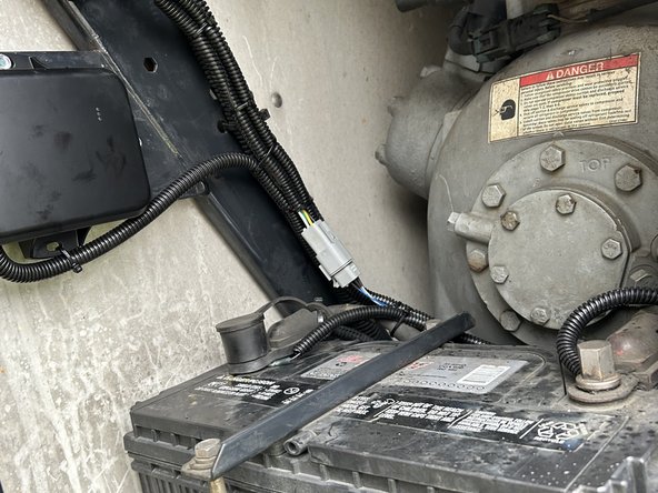
In this example installation, we connect directly to the battery of the refrigeration unit for our constant power and ground connections.
-
Some Cold Chain harnesses already contain a three-wire harness branch that can be directly connected to the GO RUGGED's HRN-RW03K4 three-wire harness. In these cases, make sure to refer to the Refrigeration Unit guides in the Cold Chain category for instructions specific to the refrigeration unit you are working on.
-
RED Battery Wire - Locate and verify a constant +12/24V Battery source.
-
BLACK Ground Wire - Locate and verify a ground source. The reference point directly comes from the battery terminal, and the refrigeration units chassis.
-
Always use a digital multimeter to locate and verify your connection points.
-
-
-
YELLOW Ignition Wire - The ignition wire must be connected to the refrigeration unit controller ignition source.
-
Verify that the ignition interface point has 12V/24V when the refrigeration unit's START / RUN switch is ON.
-
Verify that the ignition interface point has 0V when the refrigeration unit’s START / RUN switch is OFF.
-
You may need to open the controller panel to access the wires for your ignition source.
-
-
-
Turn ON the refrigeration unit.
-
-
-
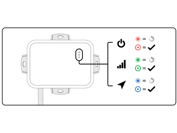
Once the GO9 RUGGED device receives power, the LEDs on the front of the device start blinking then turn solid as it goes through the following configuration and connectivity checks:
-
Red LED — Device configuration
-
Green LED — Cellular network connectivity
-
Blue LED — GPS network connectivity
-
The device emits 2 quick beeps every 60 seconds during set-up. Once all three LEDs turn solid you will hear 10 quick beeps.
-
Verify LED pattern.
-
-
-
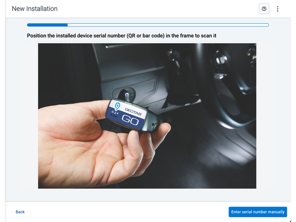
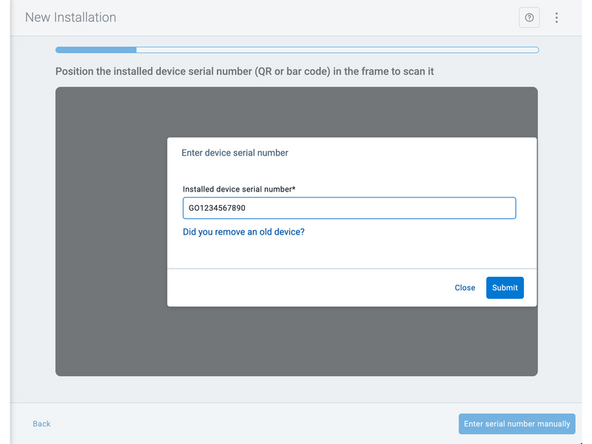
Two options are available to enter the device serial number:
-
Scan the device serial number (QR or barcode) using your mobile device.
-
Press Enter serial number manually, enter the serial number, and then press Submit.
-
If you are also removing an old device, press Did you remove an old device? and then enter the removed device serial number.
-
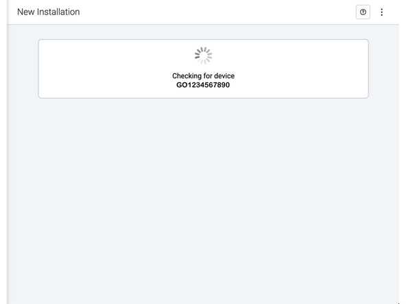
MyInstall takes a moment to check the device status.
-
-
-
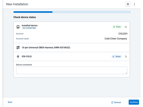
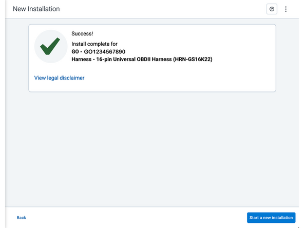
Installed device
-
Pass – The device has successfully communicated with the network in the last 24 hours.
-
Fail – The device has not communicated with the network in the last 24 hours.
-
If the device status shows as FAILED, verify the LED status and turn the ignition / engine off and on again.
-
Press Refresh to check the status again.
-
Refer to the MyInstall User Guide for detailed instructions.
-
-
-
Under Check device status, you will see the connected IOX device.
-
Press Set up device to start.
-
-
-
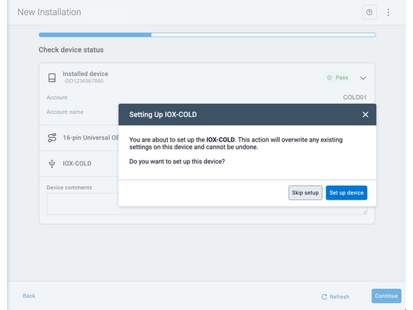
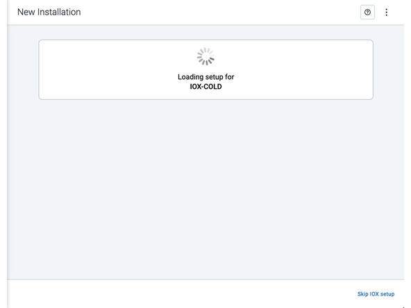
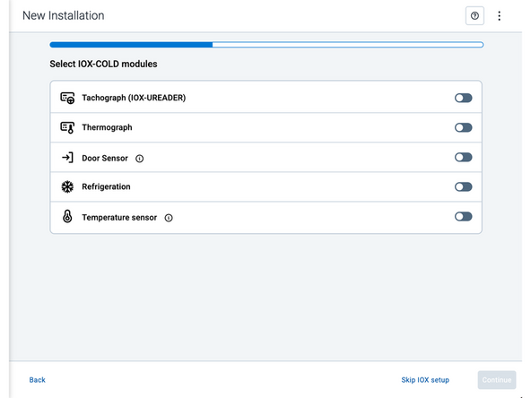
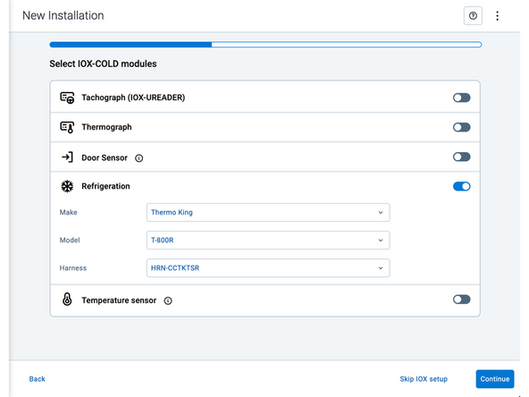
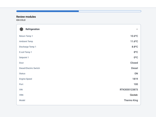
Under Select IOX-COLD modules follow the on-screen instructions to configure and finalize the IOX setup for the installation that you have performed.
-
This may involve configuring settings, or completing any necessary calibration.
-
This image shows an example of what an IOX device setup could look like. The actual screens and options may vary depending on your specific IOX device.
-
After making your selections, press Continue to configure the IOX device.
-
-
-
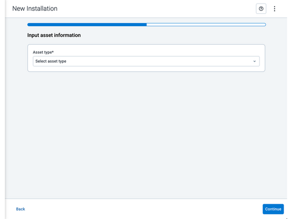
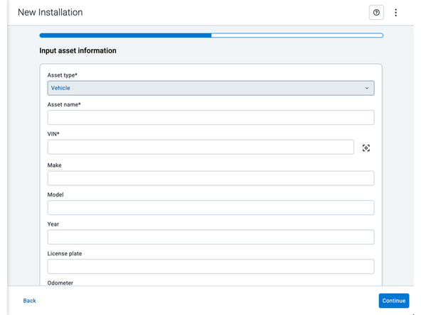
Asset name — Enter the vehicle or asset name. This field is mandatory.
-
VIN — Scan or enter the vehicle identification number (VIN). For scanning, select the scan icon [O] beside the field. This field is mandatory.
-
Make, Model, and Year — This information will be auto populated when you scan or enter a valid VIN. If it is not autopopulated, enter the information manually. NOTE: For some vehicle makes and models, the autopopulate option might not be possible.
-
License plate — Enter the vehicle license plate.
-
Odometer (GO device only) — Enter the vehicle odometer, and select the measurement unit (km or miles).
-
Engine hours (GO device only) — Enter the vehicle engine hours.
-
Camera ID (GO device only) — Scan or enter the installed camera identification (ID) number. NOTE: Depending on the camera type, the camera ID number can also be the camera’s International Mobile Equipment Identity (IMEI), or serial number. Select the information icon ⓘ to learn more about your camera’s ID number.
-
Work order reference — If applicable, enter a work reference number that is associated with the installation.
-
-
-
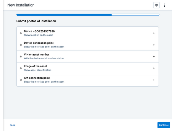
Under Submit photos of installation, upload photos of the service.
-
Press the camera icon to take a photo with your mobile device.
-
Press the plus icon (+) to attach an image from your photo gallery.
-
The number of photos required depends on the device being installed.
-
! IMPORTANT: Ensure that photos do not capture personally identifiable and confidential information.
-
-
-
The IOX-COLD RUGGED must be configured using MyInstall before verifying the LED status.
-
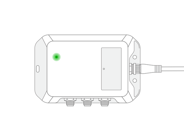
The IOX-COLD RUGGED device has a status LED that produces a series of blinks followed by a pause.
-
Ensure that the refrigeration unit's START / RUN switch is ON when checking the LED status.
-
Green LED — Solid LED - The IOX-COLD RUGGED is configured correctly and communicating with the refrigeration unit.
-
If the LED is off, or if you see a different light sequence, refer to the Troubleshooting section of the IOX-COLD RUGGED page for troubleshooting steps.
-
-
-
For the latest version of the Limitations of Use, please visit: http://goo.gl/k6Fp0w
-
Your in-vehicle devices must be kept clear of debris, water and other environmental contaminants. Failure to do so may result in units malfunctioning or short-circuiting, which can lead to a fire hazard and cause loss or serious injury.
-
Do not attempt to remove the devices from the vehicle in which they are originally installed for installation in another vehicle.
-
Not all vehicles share compatibility, and doing so may result in unexpected interactions with your vehicle, including sudden loss of power or shutdown of the vehicle’s engine while in operation or cause your vehicle to operate poorly or erratically and cause serious injury and/or vehicle damage.
-
This product does not contain any user-serviceable parts. Configuration, servicing, and repairs must only be made by an authorized reseller or installer. Unauthorized servicing of these products will void your product warranty.
-
The simplified EU declaration of conformity referred to in Article 10(9) shall be provided as follows:
-
Hereby, Geotab (Address: 2440 Winston Park Drive, Oakville, Ontario L6H 7V2, Canada, Phone number: 1 (877) 436-8221) declares that the radio equipment type ‘telematics device’ is in compliance with Directive 2014/53/EU. The full text of the EU declaration of conformity is available here.
-
WARNING: Cancer and Reproductive Harm
-