
Introduction
The IOX-ALERT allows a driver to send a notification to a dispatcher through the press of an alert button.
The Geotab HDW-IOXBUTTON (must be ordered separately) or similar momentary or ON/OFF toggle switch may be used with the IOX-ALERT.
Once pressed, the alert button signals the Geotab GO device to send a specific engine diagnostic to MyGeotab, where an Exception Rule can trigger notifications, emails or workflow.
Recommended Tools & Consumables
Hardware & Accessories


-
-
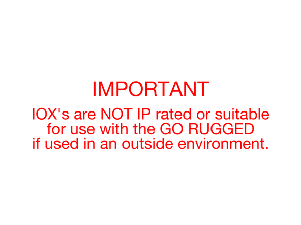
IOX's cannot be exposed to outside environments.
-
-
-
Before starting the installation, ensure the Geotab GO device is unplugged from the vehicle.
-
-
-
The IOX-ALERT has a single BLACK wire that must be connected to an external trigger button.
-
This wire can either be connected to a momentary contact (HDW-IOXBUTTON) or a ON/OFF toggle switch.
-
-
-
Always consult with the customer to determine the appropriate mounting location of the HDW-IOXBUTTON.
-
Ensure the mounting location is within reach of the driver.
-
The HDW-IOXBUTTON will require a 1/2" (13.6mm) hole to be drilled for mounting.
-
Use extreme caution when drilling holes. Before drilling, check behind the mounting location to ensure the area is clear of any obstructions or electrical wires/components/airbags.
-
Mount the HDW-IOXBUTTON button & tighten the supplied nut to no more than 1.5 Nm.
-
-
-
The IOX-ALERT has a single black wire (labelled AUX 1).
-
Connect it to one of the wires of the HDW-IOXBUTTON.
-
Connect the second wire of the HDW-IOXBUTTON to a chassis ground using a ring terminal.
-
You may need to extend the wire from the HDW-IOXBUTTON in order to reach a connection point for the chassis ground.
-
The wire and the ring terminal are not included in the IOX-ALERT kit and must be supplied by the installer.
-
Ensure all wire connection are secure.
-
-
-
Route the IOX-ALERT over to the mounting location of the GO device.
-
Remove expansion port cover on the GO device and plug the 90° Mini-USB connector of the IOX-ALERT into the GO device.
-
Secure the USB connector using a cable tie.
-
Do not overtighten the cable tie, as this can damage the USB connector.
-
Secure excess wiring with cable ties as needed.
-
Trim any excess cable tie.
-
-
-
Plug the GO Device into the vehicle interface harness.
-
Refer to the Harnesses Category for installation instructions specific to your vehicle type.
-
-
-
Start Vehicle.
-
Verify LED pattern.
-
The device emits 2 quick beeps every 60 seconds during set-up. Once all three LEDs turn solid you will hear 10 quick beeps.
-
-
-
All in-vehicle devices and related cabling must be securely fastened and kept clear of all vehicle controls, airbags, and gas, brake and clutch pedals.
-
This requires the use of a cable tie when securing the device or any extension harness to the OBD connector, securing both sides of the harness. If you do not use a cable tie, vibration in the vehicle can lead to a loose connection which could cause the vehicle’s engine computer to fail, causing potential loss of vehicle control and serious injury.
-
Inspect devices and cabling regularly to ensure all devices and cabling continue to be securely attached.
-
If at any point after an in-vehicle device is installed a warning light illuminates on the vehicle dash or the vehicle stalls or has a marked drop in performance, shut off the engine, remove the device, and contact your reseller. Continuing to operate a vehicle with these symptoms can cause loss of vehicle control, and serious injury.
-
-
-
Navigate to one of the following:
-
-
-
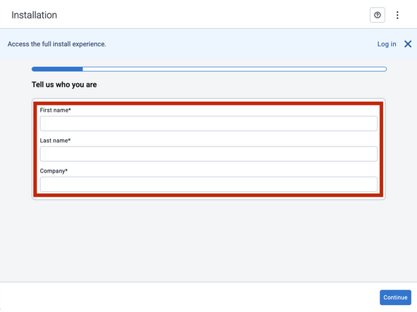
Note that the following steps are for the public version of MyInstall.
-
If you have an installer MyAdmin account, use this link
-
This link is also accessible via the MyInstall Public page.
-
-
-
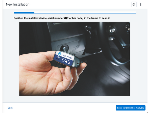
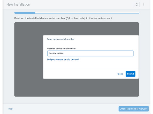
Two options are available to enter the device serial number:
-
Scan the device serial number (QR or barcode) using your mobile device.
-
Press Enter serial number manually, enter the serial number, and then press Submit.
-
If you are also removing an old device, press Did you remove an old device? and then enter the removed device serial number.
-
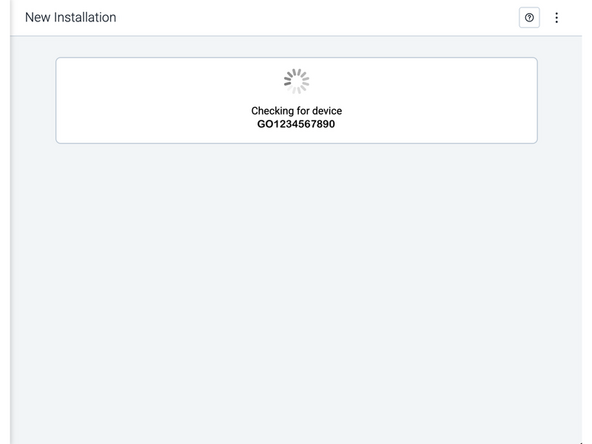
MyInstall takes a moment to check the device status.
-
-
-
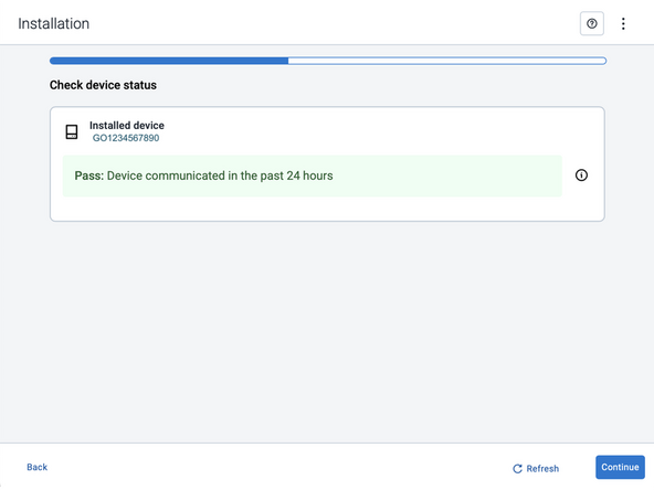
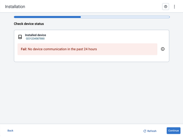
Installed device
-
Pass – The device has successfully communicated with the network in the last 24 hours.
-
Fail – The device has not communicated with the network in the last 24 hours.
-
If the device status shows as FAILED, verify the LED status and turn the ignition / engine off and on again.
-
Press Refresh to check the status again.
-
Refer to the MyInstall User Guide for detailed instructions.
-
-
-
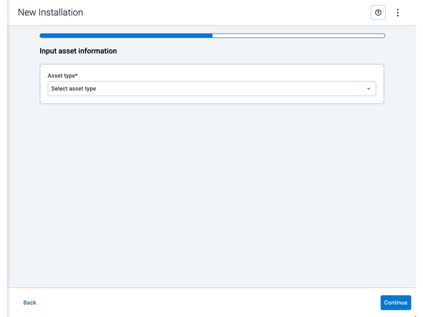
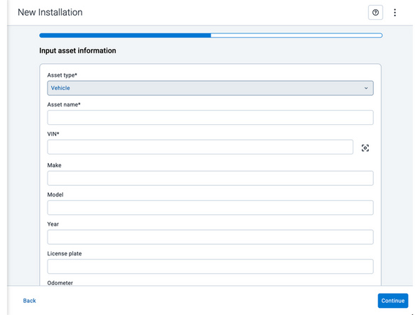
Asset name — Enter the vehicle or asset name. This field is mandatory.
-
VIN — Scan or enter the vehicle identification number (VIN). For scanning, select the scan icon [O] beside the field. This field is mandatory.
-
Make, Model, and Year — This information will be auto populated when you scan or enter a valid VIN. If it is not autopopulated, enter the information manually. NOTE: For some vehicle makes and models, the autopopulate option might not be possible.
-
License plate — Enter the vehicle license plate.
-
Odometer — Enter the vehicle odometer, and select the measurement unit (km or miles).
-
Engine hours — Enter the vehicle engine hours.
-
Camera ID (GO device only) — Scan or enter the installed camera identification (ID) number. NOTE: Depending on the camera type, the camera ID number can also be the camera’s International Mobile Equipment Identity (IMEI), or serial number. Select the information icon ⓘ to learn more about your camera’s ID number.
-
Work order reference — If applicable, enter a work reference number that is associated with the installation.
-
-
-
For the latest version of the Limitations of Use
-
Your in-vehicle devices must be kept clear of debris, water and other environmental contaminants. Failure to do so may result in units malfunctioning or short-circuiting, which can lead to a fire hazard and cause loss or serious injury.
-
This product does not contain any user-serviceable parts. Configuration, servicing, and repairs must only be made by an authorized reseller or installer. Unauthorized servicing of these products will void your product warranty.
-
The simplified EU declaration of conformity referred to in Article 10(9) shall be provided as follows:
-
Hereby, Geotab (Address: 2440 Winston Park Drive, Oakville, Ontario L6H 7V2, Canada, Phone number: 1 (877) 436-8221) declares that the radio equipment type ‘telematics device’ is in compliance with Directive 2014/53/EU. The full text of the EU declaration of conformity is available here.
-
WARNING: Cancer and Reproductive Harm
-



Cancel: I did not complete this guide.
One other person completed this guide.

Team
