Introduction
For more information see 9-pin Heavy Duty T-harness Kit Compatible with GO10 and GO10 Plus - HRN-XGS09K2 support document.
Recommended Tools & Consumables
Hardware & Accessories
-
-
WARNING! Only use Geotab telematics devices with Geotab-approved harnesses acquired from Geotab-authorized channels. Use of non-Geotab harnesses from unauthorized channels can cause serious safety risks, including fire, and can lead to serious personal injury and/or damage to the vehicle.
-
IMPORTANT: Always use a vehicle-specific harness when offered by Geotab or the vehicle manufacturer to avoid possible damage to the GO device. Some vehicles have multiple diagnostic connectors to choose from when installing a GO device.
-
For more information on Geotab harnesses and adapters, refer to the Harness Identification and Application & Harness Assessment Cheat Sheet & Geotab Truck Solution - Harness Identification and Application
-
If a longer length is required to facilitate installation, connect a straight harness to a T-harness. Ensure that the total harness length does not exceed 2 meters (6.5 feet), because this can compromise the integrity of the data and cause issues with the vehicle’s Engine Control Unit (ECU).
-
For more details on compliance information and applicable products, contact your Authorized Reseller.
-
-
-
Some installations are not straightforward and must be completed by an Authorized Installer to ensure a secure installation.
-
Ensure you use enough cable ties to secure both the device and the harness to the vehicle. An unsecure device can result in poor electric and/or data connections, which can lead to short circuits and fires or cause malfunctions of vehicle controls that can result in serious personal injury or significant damage to the vehicle.
-
Some examples requiring professional installation from an Authorized Installer are:
-
The OBD port location is such that the device could protrude or interfere when entering or exiting the vehicle, or located where it could be inadvertently kicked or bumped during vehicle operation. The device isn't fully secured and may be able to vibrate loose or get kicked or knocked. An electrical harness or additional wiring is required.
-
Vehicle mounting modifications are required to secure the device, such as removing of panels. The OBD connector has been deformed/damaged or there is physical damage visible to the electrical wiring.
-
The device does not power on and beep six times when first installed.
-
The installer questions their ability to complete a secure installation according to these instructions.
-
-
-
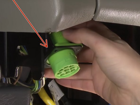
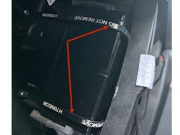
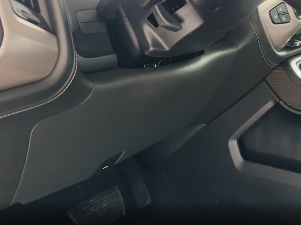
Locate and un-mount the vehicle diagnostic connector.
-
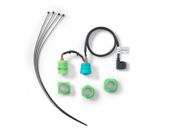
Match the diagnostic connector to one of the adapters included in the kit.
-
See here for adapter identification
-
-
-
If your vehicle does not use the pre-installed Adapter 1, use the steps below to replace with the required adapter.
-
There are no special tools needed to change the adapter.
-
-
-
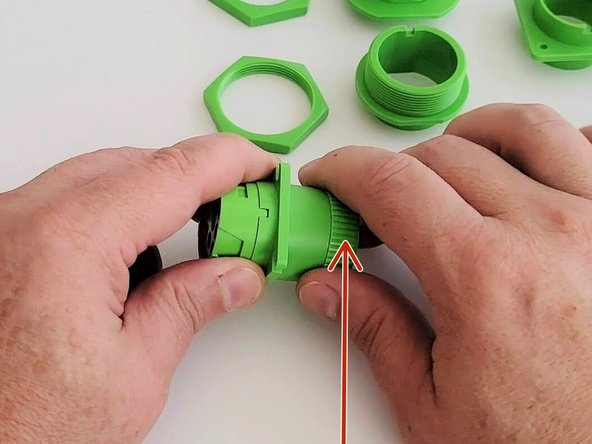
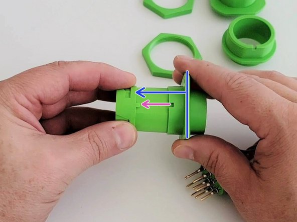
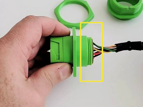
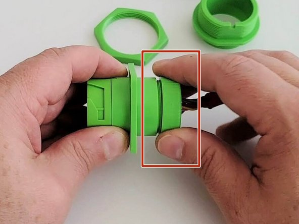
Remove the screw cap at the back of the connector and slide it slightly away from the connector.
-
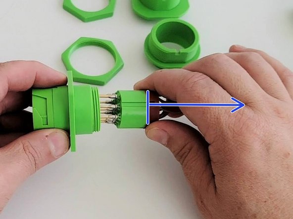
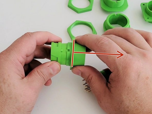
Pull the connector housing and adapter assembly away from the connector cartridge and harness.
-
-
-
-
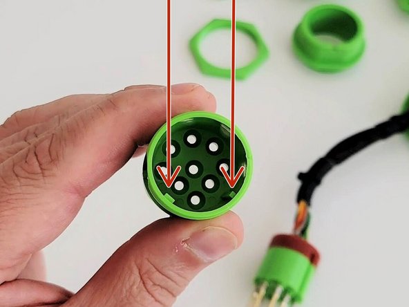
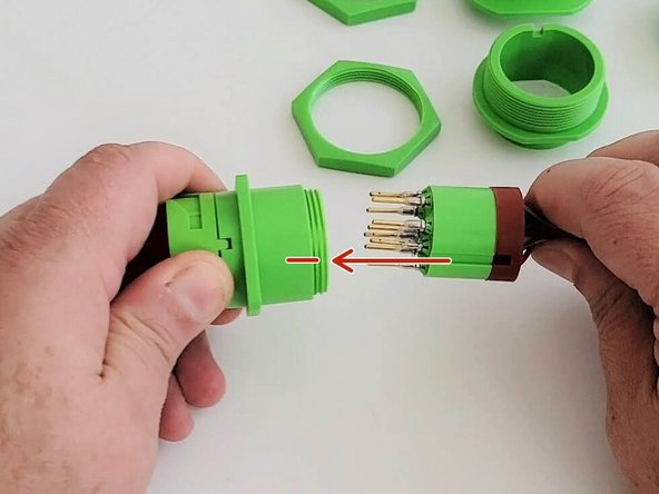
Align the keys & keyways and slide the connector cartridge into the connector housing.
-
-
-
-
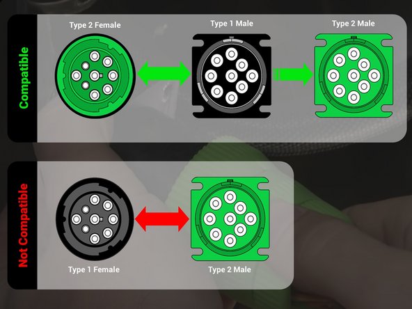
As seen in this compatibility graphic, the HRN-XDM09T2 harness is backward compatible with Type 1 (black 9 pin) equipped vehicles as well as newer Type 2 (green).
-
Older Type 1 (black) diagnostic harnesses should not be reused with Type 2 (green) vehicles as they are not compatible.
-
-
-
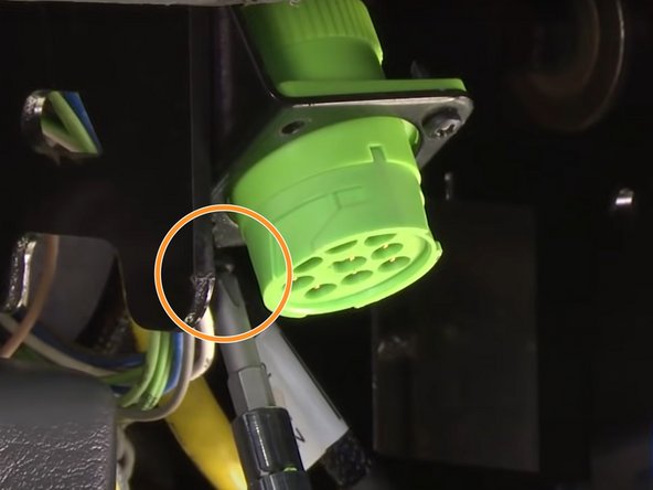
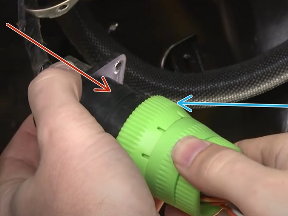
Connect the OEM 9 pin diagnostic connector into the HRN-XDM09T2 harness.
-
Twist the locking collar to secure connection.
-
It is recommended to secure this connection with a cable tie if the collar does not lock adequately.
-
Secure this connection as up and out of view as possible using cable ties.
-
Ensure cable does not interfere with any moving parts.
-
-
-
If installing an IOX accessory please use the correct guide from here before performing the steps below.
-
-
-
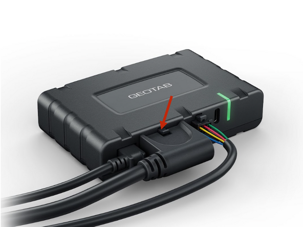
Plug Harness into the GO Device.
-
Be sure it clips in place. Due to this clip securing the connection a cable tie is not required.
-
-
-
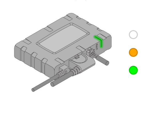
After 30 seconds, you should see a solid green light. If not, look for the LED pattern and troubleshoot using the below steps:
-
Slowly flashing WHITE - Initializing/waking up - Do not power off device, wait for it to finish.
-
Quickly flashing WHITE - Firmware updating - Do not power off device, wait for update to finish.
-
Quickly flashing ORANGE - Weak/No cell signal - Move vehicle to area with better cellular coverage.
-
Flashing ORANGE twice - Weak/No GPS signal - Ensure device has a clear view to the sky.
-
Solid GREEN - Device is operating normally - No action needed.
-
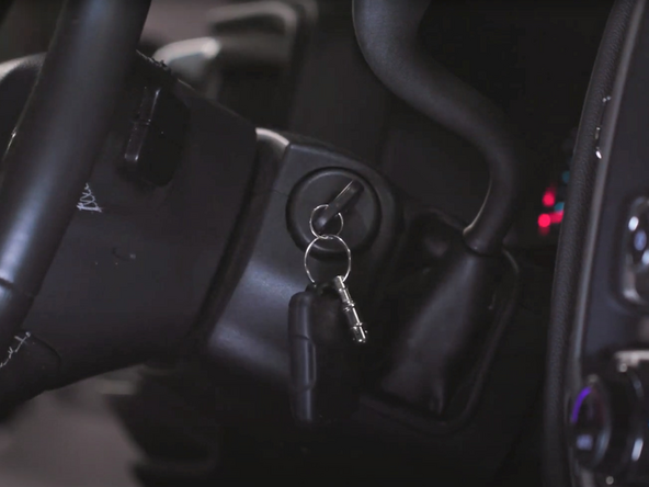
Quickly flashing GREEN - No ignition - Ensure Vehicle ignition is on.
-
Flashing GREEN every 3 seconds - Light Sleep - Device is sleeping, no action is needed.
-
-
-
Route device to mounting location as needed.
-
Ensure cable does not interfere with any moving parts.
-
Sercure harness as needed with cable ties.
-
Secure device using 2 cable ties.
-
To ensure good data quality, the decice must be firmly secured with no free movement!
-
-
-
Navigate to one of the following:
-
-
-
Note that the following steps are for the public version of MyInstall.
-
If you have an installer MyAdmin account, use this link
-
This link is also accessible via the MyInstall Public page.
-
-
-
Please visit Limitations of Use
-
Your in-vehicle devices must be kept clear of debris, water and other environmental contaminants. Failure to do so may result in units malfunctioning or short-circuiting, which can lead to a fire hazard and cause loss or serious injury.
-
This product does not contain any user-serviceable parts. Configuration, servicing, and repairs must only be made by an authorized reseller or installer. Unauthorized servicing of these products will void your product warranty.
-
The simplified EU declaration of conformity referred to in Article 10(9) shall be provided as follows:
-
Hereby, Geotab (Address: 2440 Winston Park Drive, Oakville, Ontario L6H 7V2, Canada, Phone number: 1 (877) 436-8221) declares that the radio equipment type ‘telematics device’ is in compliance with Directive 2014/53/EU. The full text of the EU declaration of conformity is available here.
-
WARNING: Cancer and Reproductive Harm
-