Introduction
Installation instructions for the IOX-KEYLESS solution with SID (Starter Inhibit Device) using the HRN-SIFUSETAP harness.
-
-
WARNING! Installation of this product into vehicle systems requires professional installation by a qualified technician who is thoroughly familiar with any circuits involved.
-
Installing the Geotab SID solution requires real-time access to the host vehicle wire interface diagrams for starter control (i.e. ALLDATA™, WireSheet™, Mitchell1 ProDemand™ / eAutoRepair™ or equivalent). Typically, the diagrams are provided to car security solution installers.
-
-
-
WARNING! The Geotab SID solution must not be installed in such a manner where it has the potential to disable propulsion and/or prevent vehicle control while the vehicle is in motion.
-
Never install a circuit interrupt on any circuit that may interfere with the safe operation of a vehicle or cause the engine to stop while the vehicle is in motion — such as fuel lines, brake switch, or multiplexed circuits.
-
Some vehicles stop the engine every time the vehicle comes to a stop, and automatically restarts the engine upon pressing the accelerator pedal.
-
Installers in these vehicles need to ensure activation of the Starter Inhibit feature does not disable the vehicle in a precarious location (i.e. a busy intersection) and does not leave the vehicle unable to move to a safe location or other direct or indirect effects resulting from the installation of the Starter Inhibit feature.
-
-
-
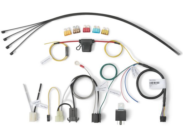
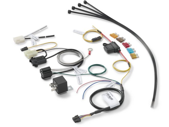
This installation guide covers the installation of the HRN-SIFUSETAP - Starter Inhibit Harness for IOX-KEYLESS.
-
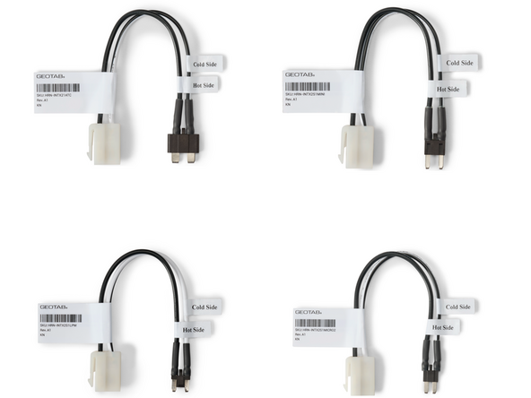
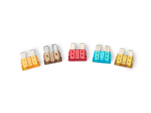
The following fuse interrupters are available to use with the HRN-SIFUSETAP harness to interrupt a circuit in the vehicles fuse panel:
-
HRN-INTX21ATC - ATC Fuse Interrupter
-
HRN-INTX2S1MINI - Mini Fuse Interrupter
-
HRN-INTX2S1LPM - LP Mini Fuse Interrupter
-
HRN-INTX2S1MICRO2 - Micro2 Fuse Interrupter
-
-
-
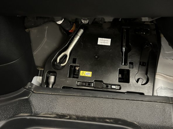
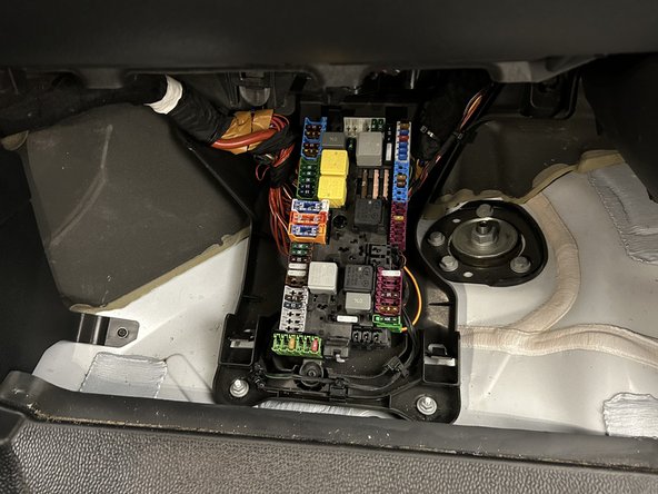
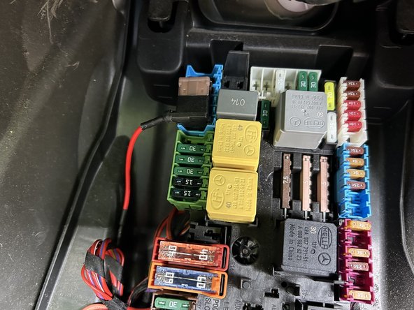
Locate and access the vehicles fuse panel.
-
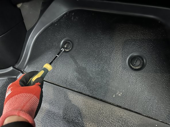
Some vehicles may require you to remove dash panels / covers to access the fuse panel.
-
-
-
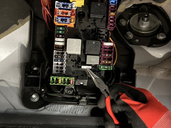
Locate and test the fuse for Starter Interrupt using a Digital Multimeter.
-
Ensure the fuse does not interfere with safe operation of the vehicle and does not cause an permanent fault codes to be displayed on the vehicle dashboard.
-
The fuse used for Starter Interrupt should prevent the vehicle from starting when the engine is off.
-
The engine should remain running if the fuse is disconnected from the vehicle while the engine is running.
-
It is highly recommended to refer to vehicle wire interface diagrams for starter control (i.e. ALLDATA™, WireSheet™, Mitchell1 ProDemand™ / eAutoRepair™ or equivalent) to locate the starter wire in the vehicle.
-
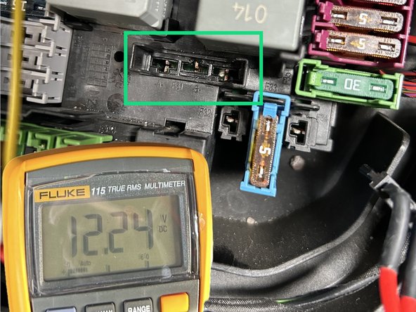
Remove the fuse and verify the HOT side of the fuse slot with a digital multimeter.
-
When testing the HOT side of fuse slot, also check to see if the fuse is a Constant 12V/24V or a Switched Ignition circuit.
-
-
-
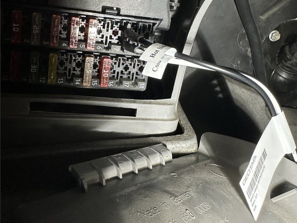
Insert the Fuse Interrupter into the fuse slot.
-
The HRN-INTX21ATC - ATC Fuse Interrupter is used in this example.
-
Ensure to use the correct Fuse Interrupter for your application.
-
Ensure the Black Wire on the Fuse Interrupter is connected to the HOT side of the fuse slot.
-
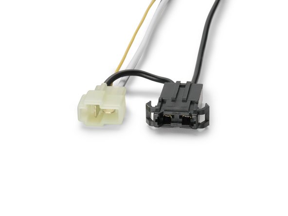
Connect the White 2-pin Molex connector from the Fuse Interrupter to the White 2-pin Molex connector on the HRN-SIFUSETAP harness.
-
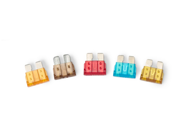
Using the supplied fuses, insert a fuse of the same rating as the one that was removed from the vehicle into the Black Fuse holder on the HRN-SIFUSETAP harness.
-
Ensure the connection is secure.
-
-
-
The supplied flying lead harness in the HRN-SIFUSETAP harness kit may be used instead of the Fuse Interrupters to interrupt the starter circuit.
-
Using a digital multimeter, locate the START (cranking) wire — the wire that is at 12V / 24V when the key is in the start position.
-
It is highly recommended to refer to vehicle wire interface diagrams for starter control (i.e. ALLDATA™, WireSheet™, Mitchell1 ProDemand™ / eAutoRepair™ or equivalent) to locate the starter wire in the vehicle.
-
Cut the starter wire.
-
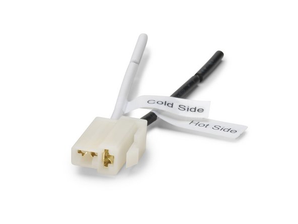
Connect the Black wire (HOT SIDE) to the +12V/24V signal and the White wire (COLD SIDE) to the starter.
-
For all connections, strip 1/2" (15 mm) of insulation, solder, and insulate the connection using heat shrink or electrical tape. Ensure the connections are secure.
-
Connect the White 2-pin Molex connector from the Fuse Interrupter to the White 2-pin Molex connector on the HRN-SIFUSETAP harness.
-
Using the supplied fuses, insert a fuse of the same rating as the starter circuit of the vehicle into the Black Fuse holder on the HRN-SIFUSETAP harness.
-
-
-
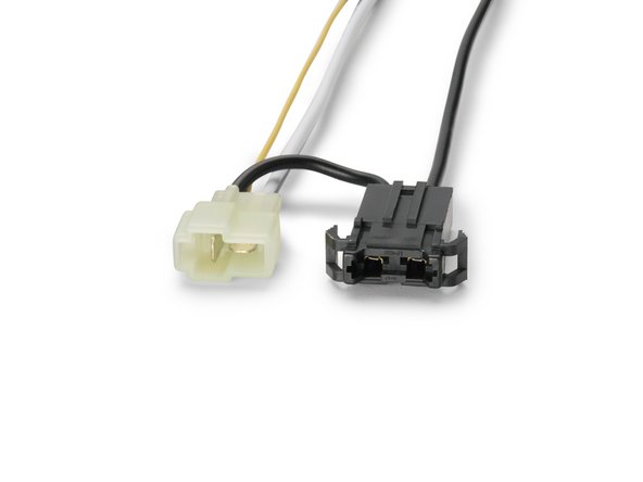
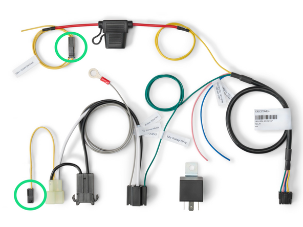
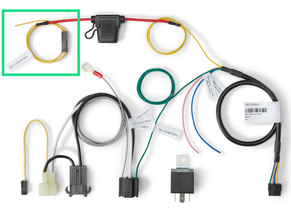
If the HOT side of the Fuse Interrupter is on a switched ignition source, proceed to connect the Black molex connector (Yellow wire) from the HRN-SIFUSETAP harness to the Black molex connector from the Fuse Interrupter connection point (2-pin white molex connector).
-
If the HOT side of the Fuse Interrupter is on a constant +12V/24V source then proceed to the next step.
-
Ensure the connection is secure.
-
-
-
Use the Yellow Ignition pigtail provided with the HRN-SIFUSETAP harness kit to find a true Ignition source +12V / +24V.
-
This ignition source is used to energize the relay.
-
The Ignition source should have +12V / +24V when the Ignition switch is in the ON/RUN and Start positions and should have 0V when the Ignition switch is in ACC or OFF positions.
-
IMPORTANT: Do not connect the yellow wire to a constant power source nor to the vehicle's battery. This can result in the relay constantly draining the vehicle's battery.
-
A Fuse adapter may be used to connect to a location in the fuse panel for the ignition source.
-
The fuse adapter must be supplied by the installer / technician.
-
Use a Digital Multimeter to verify before making the connection.
-
Ensure the connection is secure.
-
-
-
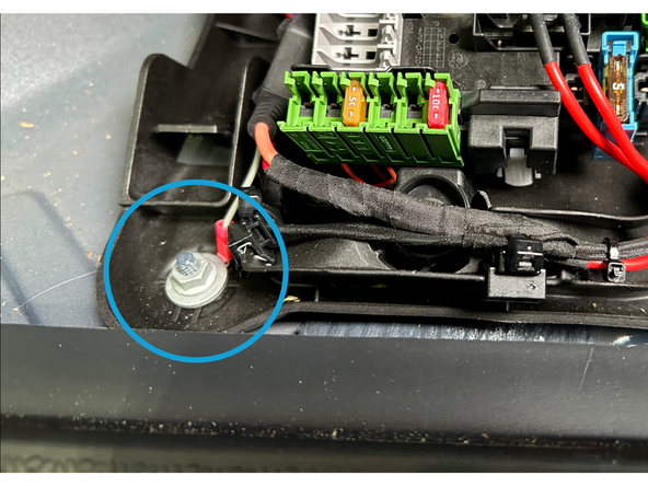
Locate a suitable chassis-ground point.
-
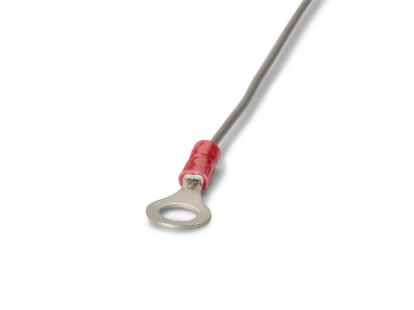
Connect the ring terminal from the HRN-SIFUSETAP harness to the chassis ground.
-
A self-tapping screw can be used to secure the ring terminal to a part of the metal dash frame.
-
IMPORTANT: Ensure there is no wiring or objects behind the location of the ring terminal prior to drilling.
-
Ensure the connection is secure.
-
-
-
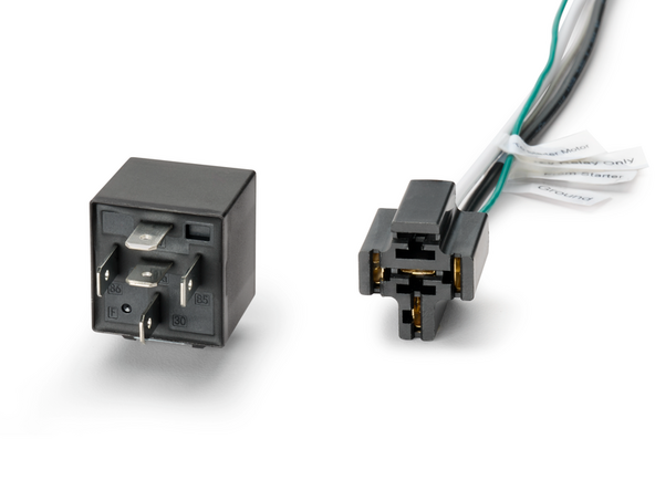
Plug the supplied relay into the 5-pin relay socket.
-
-
-
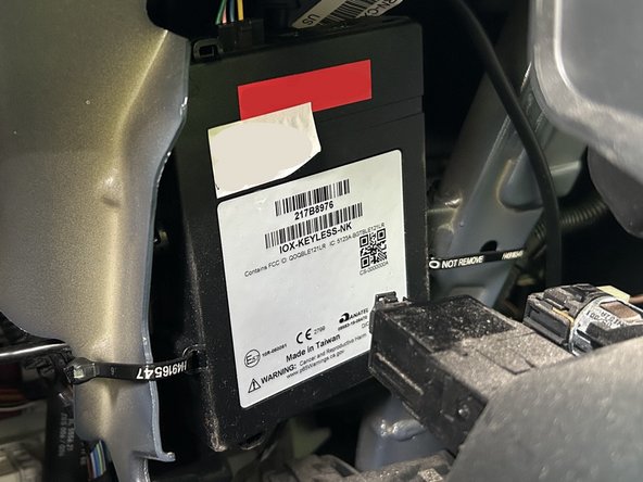
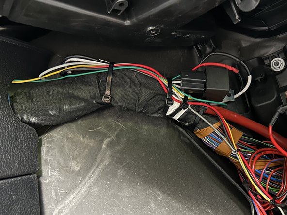
Route the HRN-SIFUSETAP harness to the mounting location of the IOX-KEYLESS
-
It's important to avoid any pinch points and sharp corners when running wires.
-
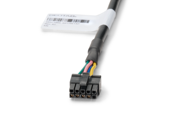
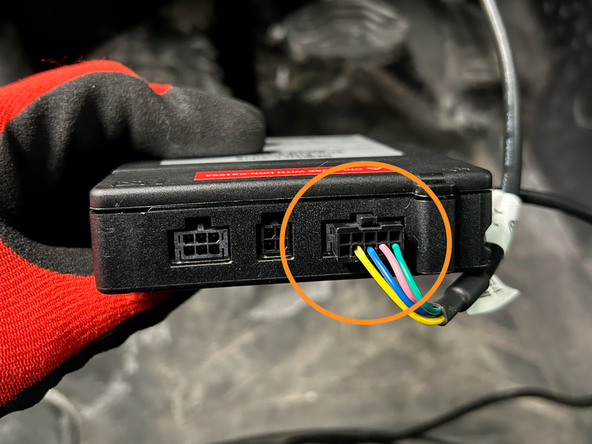
Connect the 10-pin Black Molex Connector from the HRN-SIFUSETAP harness to the IOX-KEYLESS.
-
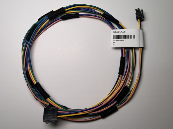
The HRN-GX04S6 harness may be used to extend the HRN-SIFUSETAP harness if additional length is needed to reach the mounting location of the IOX-KEYLESS.
-
Ensure the connection is secure.
-
-
-
Secure excess harness as needed with cable ties
-
Ensure the harness does not interfere with any moving parts or safe operation of the vehicle.
-
Trim any excess cable tie
-
-
-
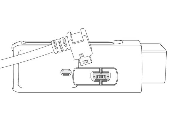
Connect the IOX-KEYLESS to the GO device.
-
Remove the expansion port cover and plug in the 90° USB connector from the IOX-OUTPUTM into the GO device.
-
Secure the connection with a cable tie.
-
Ensure the cable tie is firmly situated in the grooves, both on the plug and the GO device, to prevent tampering.
-
DO NOT OVER-TIGHTEN! The connector on the device can be damaged if over-tightened.
-
Trim any excess cable tie.
-
-
-
Installations for the IOX-KEYLESS SID (Starter Interrupt Device) solution require a GO device and a T-harness. Refer to the HRN-GS16K2-LD Standard LD 16-Pin T-Harness Kit guide for installation instructions.
-


Team
