Recommended Tools & Consumables
Hardware & Accessories
-
-
Do not attempt to install, reconfigure or remove any product from a vehicle while the vehicle is in motion or otherwise in operation. All installation, configuration or removal must be done only in stationary vehicles which are securely parked.
-
Attempting to service devices while the vehicle is in motion could result in malfunctions or accidents, leading to death or serious personal injury.
-
-
-
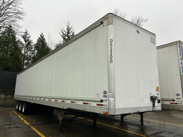
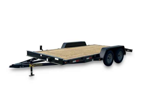
The HRN-NATRL harness is designed to be installed into a variety of trailers.
-
-
-
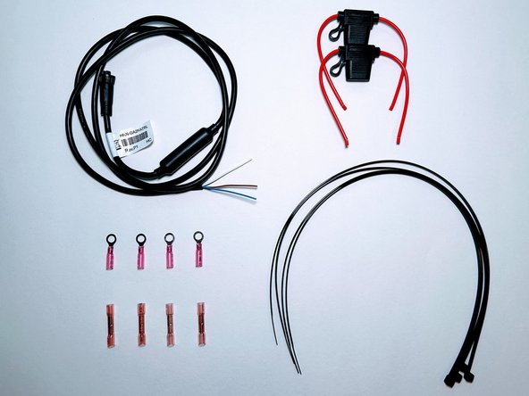
The HRN-NATRL kit contains: HRN-NATRL Harness & HRN-2AFUSEKIT
-
-
-
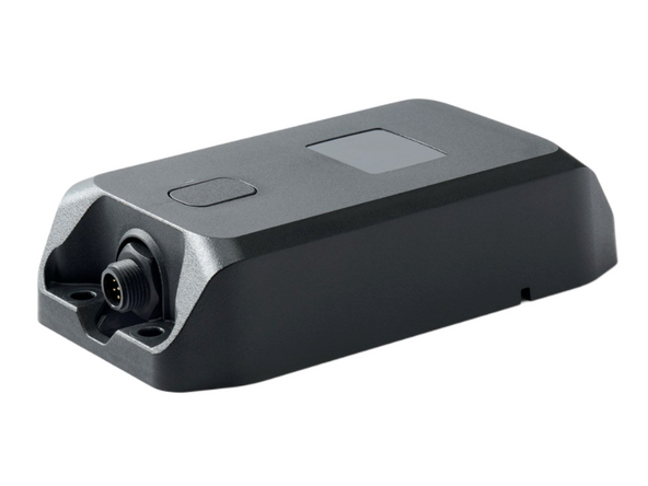
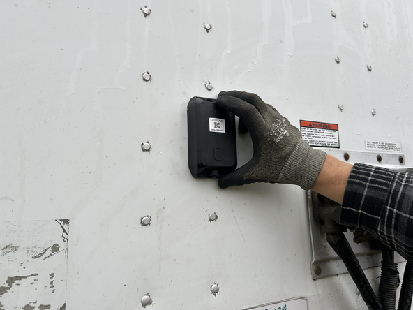
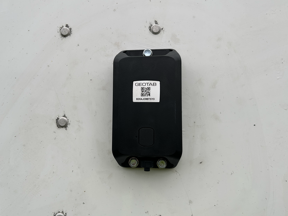
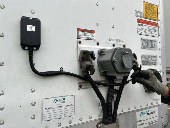
Find a suitable location to install the device on your asset.
-
The GO Anywhere 2 must have optimal line of sight to the sky with no metal obstructions that interfere with the signal.
-
Ensure the surface that you are mounting to has a solid backing where the screws will hold the device securely.
-
Mounting to thin surfaces may lead to the screws backing out due to road vibration.
-
-
-
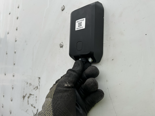
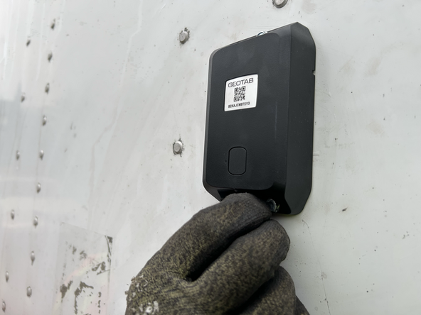
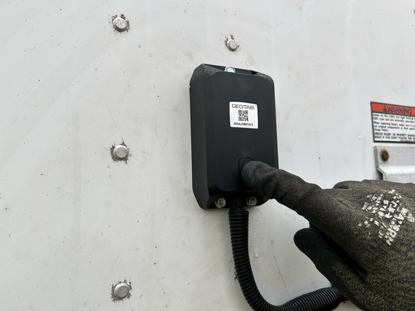
The GO Anywhere 2 device should be mounted with the connector facing downwards to prevent water intrusion.
-
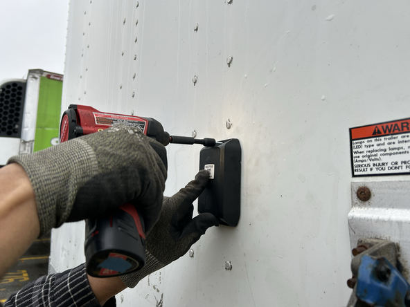
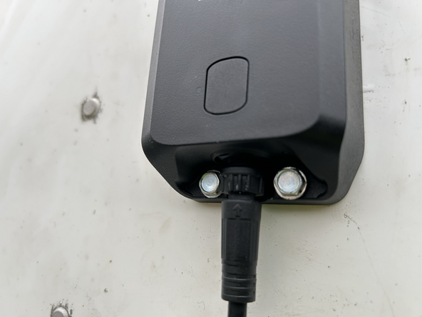
Using the supplied 3 x self drilling screws mount the GO Anywhere 2 device.
-
Before drilling, check behind the mounting location to ensure the area is clear of any obstructions or electrical wires/components.
-
-
-
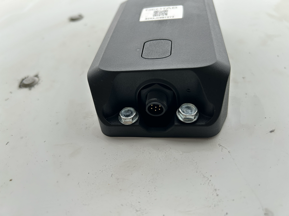
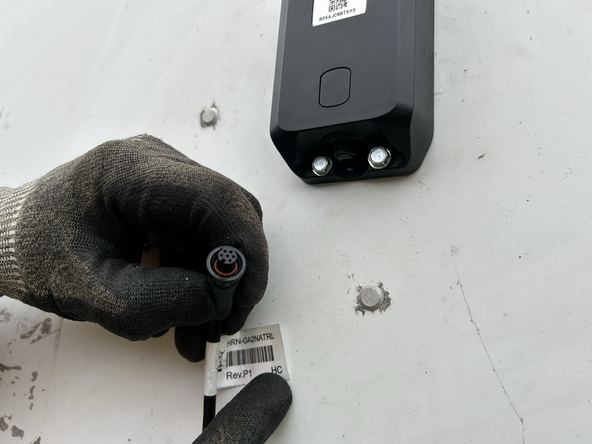
Remove the protective cap on the bottom of the GO Anywhere 2 device.
-
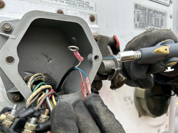
Use dielectric grease whenever connections may be exposed to moisture.
-
-
-
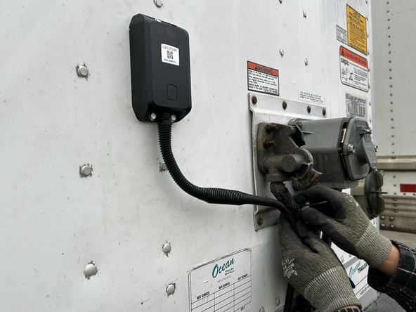
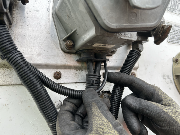
Ensure you use wire loom to protect the wires.
-
Secure excess wiring with cable ties and clamps as needed.
-
The HRN-NATRL harness can be cut to length if necessary.
-
-
-
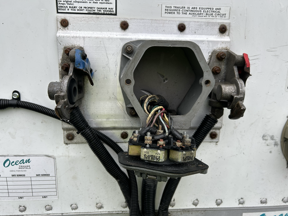
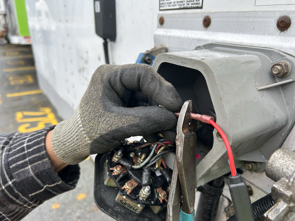
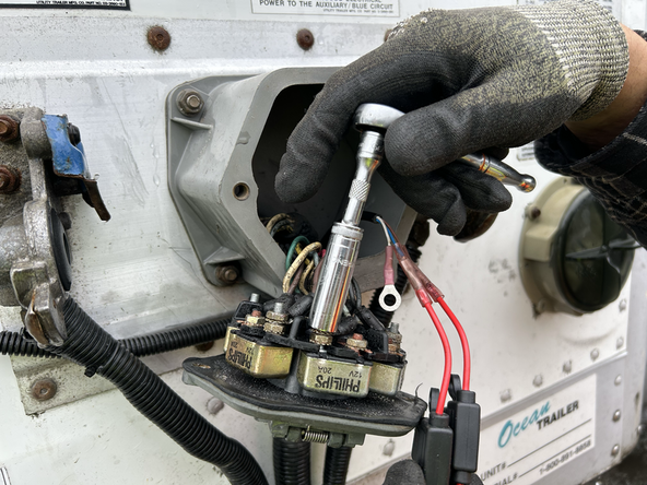
Route the wire through existing grommets if available.
-
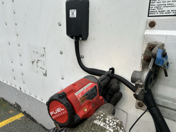
In some cases you may need to drill a hole to access the trailers connection point.
-
Before drilling, check behind the location to ensure the area is clear of any obstructions or electrical wires/components.
-
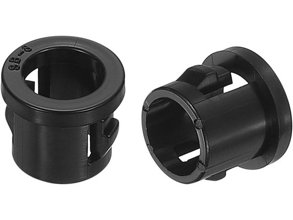
Use the appropriate grommet to prevent wire chafing.
-
-
-
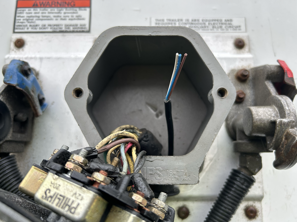
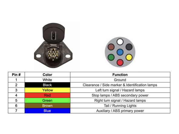
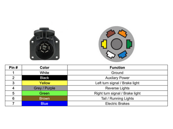
WHITE (HRN-NATRL) - Ground (Pin 1)
-
BROWN (HRN-NATRL) - Tail / Running Lights (Pin 6)
-
BLUE (HRN-NATRL) - Auxiliary / ABS primary power (Pin 7)
-
-
-
WHITE (HRN-NATRL) - Ground (Pin 1)
-
BROWN (HRN-NATRL) - Tail / Running Lights (Pin 6)
-
BLUE (HRN-NATRL) - Auxiliary power (Pin 2)
-
NOTE: Pin 2 (Black Wire) may be constant power or ignition power. You must verify this. If Constant power, to avoid vehicle battery drain, be sure to disconnect the trailer connector from the vehicle when not in use.
-
-
-
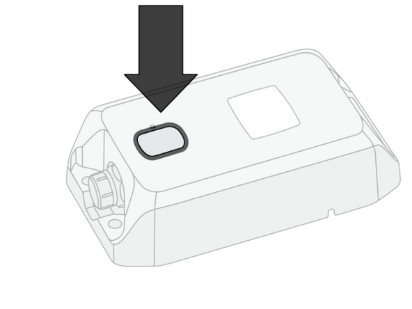
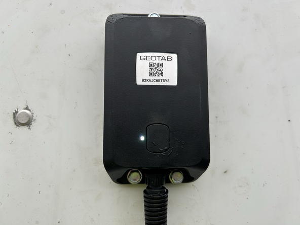
Begin activation by pressing the button on the device.
-
For optimal performance, activate the device in an area with good cellular coverage and a clear view of the sky for GNSS/GPS - outdoors are best. The activation process may take up to five minutes.
-
LED state - WHITE - Slow Flash
-
Status - Activation in progress.
-
Action - Do not unplug or touch the device.
-
LED state - GREEN - Fast flash for 15 seconds
-
Status - Device is battery-only, or wired and ignition is not detected.
-
Action - No action required.
-
-
-
LED state - ORANGE - 2 x Flash every 15 seconds
-
Status - No (or weak) cell service.
-
Action - Move asset to an area with cellular coverage. Press button to re-attempt activation.
-
If activation is unsuccessful, the device will automatically retry. You can manually force a retry by pressing the device's button.
-
-
-
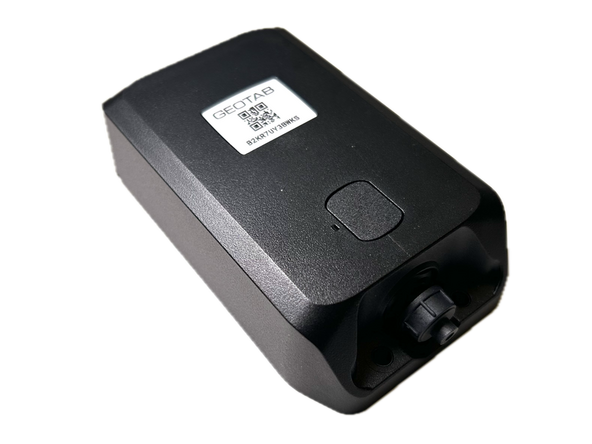
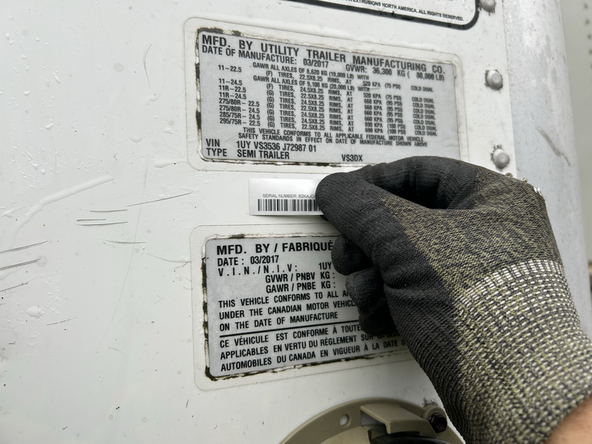
Place the serial number sticker in a suitable location for future reference.
-


Team

Authors: Field Service Install Member of Authors: Field Service Install
3 Members
122 Guides authored