
Recommended Tools & Consumables
Hardware & Accessories
-
-
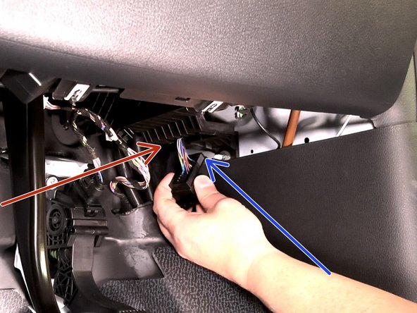
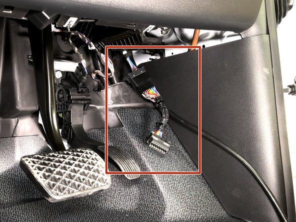
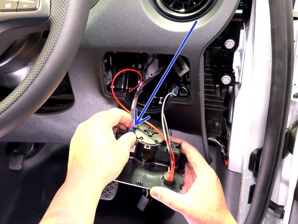
Locate & remove the OEM OBDII connector from its OEM location
-
Connector bracket is secured with (2) T-20 screws.
-
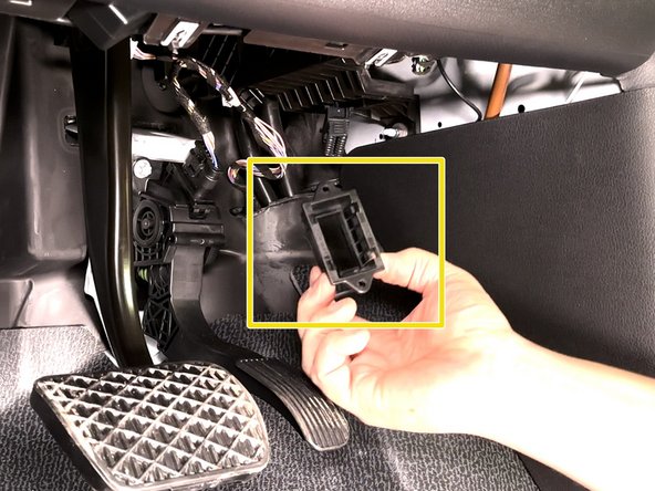
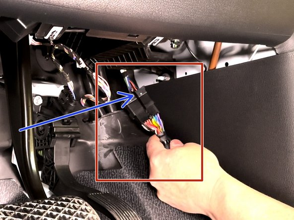
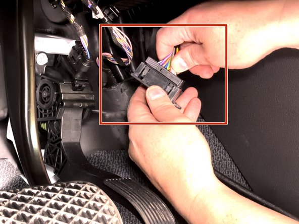
Once removed slide the grey lock away from the bracket to release the connector from the bracket.
-
The bracket will be reused, set aside for future step.
-
-
-
-
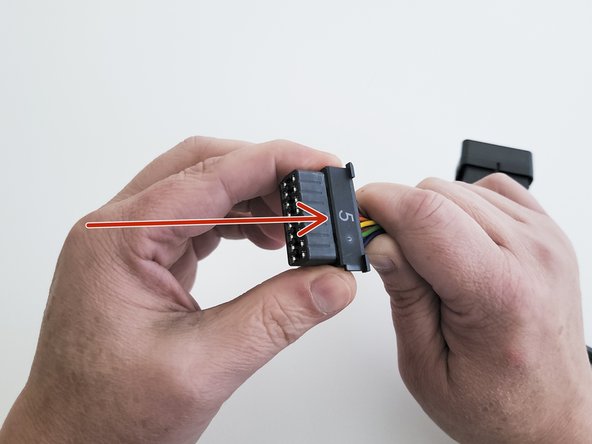
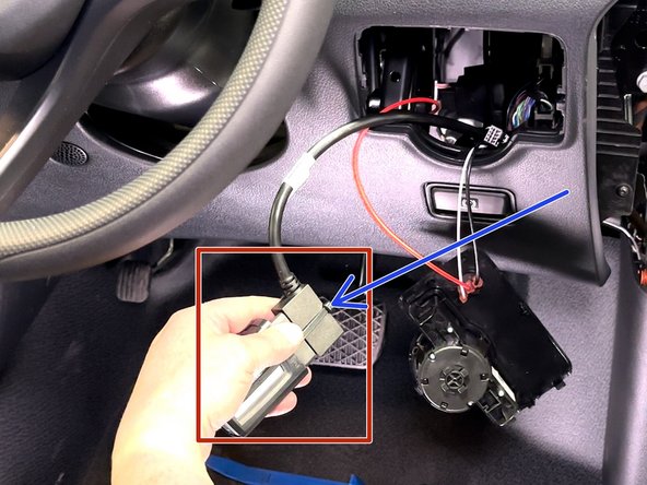
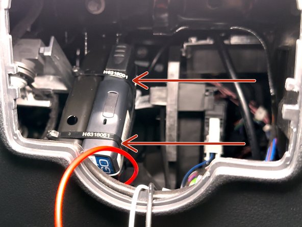
Install adapter #5 onto the connector housing.
-
In most cases the groove should be visible once the adapter is completely seated.
-
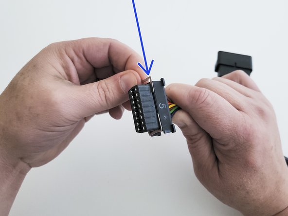
Slide the metal clips into the groove to retain the assembly
-
If the groove is not visible the adapter is likely installed backwards.
-
-
-
Plug the female connector from the T-harness into the OEM OBDII connector.
-
Secure connection with a cable tie.
-
Trim excess cable tie flush!
-
-
-
Plug the GO device into remaining end of the harness.
-
Secure the device to the harness with included cable tie.
-
Trim excess cable tie flush.
-
Every device has a black serialized cable tie included & should be used in this step.
-
-
-
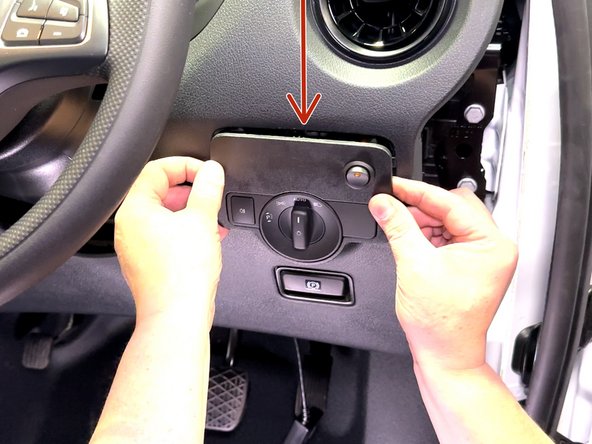
Route device and harness to mounting location as needed.
-
Ensure cable does not interfere with any moving parts & secure harness as needed with cable ties.
-
Secure device using 2 cable ties.
-
This bracket is an acceptable location to secure the device.
-
To ensure reporting quality the device must be secured with no free movement!
-
Device must not be secured with bottom side facing in direct contact of metal!
-
In this example the bottom of the device (blue side of the GO device label) faces away from the bracket it's secured to.
-

Team

Authors: Field Service Install Member of Authors: Field Service Install
2 Members
10 Guides authored