v1.4

Minor Versionm

by Jason Fox

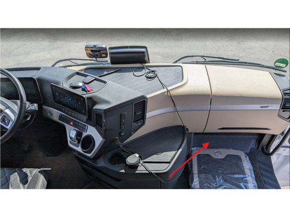
  1. Access the fuse-panel located at the bottom of the dashboard in the passenger's footwell behind a plastic cover clearly labeled "OBD"
    • Access the fuse-panel located at the bottom of the dashboard in the passenger's footwell behind a plastic cover clearly labeled "OBD"

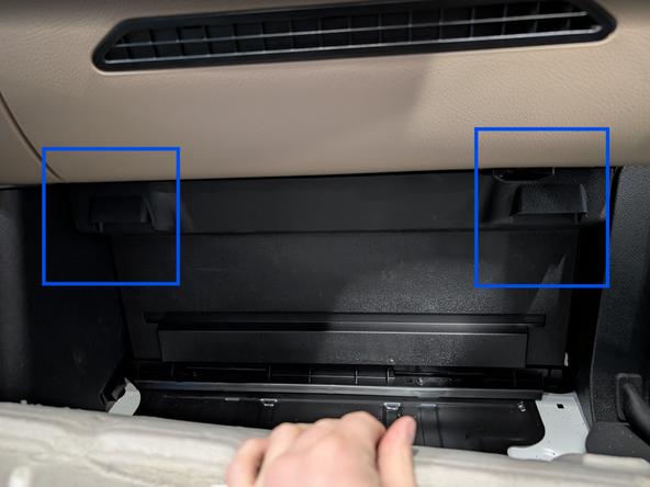
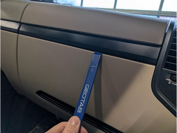
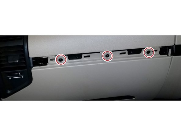
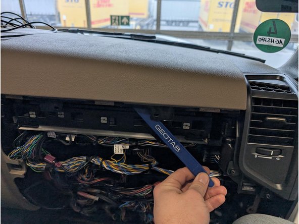
  2. Remove the kick-panel underneath the dashboard Use a panel-tool or similar tool to unclip and remove the cover-strip across the centre of the dashboard Use a size T20 Torx-driver to remove the three screws, then unclip and remove the bottom panel of the dashboard.
    • Remove the kick-panel underneath the dashboard

    • Use a panel-tool or similar tool to unclip and remove the cover-strip across the centre of the dashboard

    • Use a size T20 Torx-driver to remove the three screws, then unclip and remove the bottom panel of the dashboard.

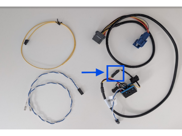
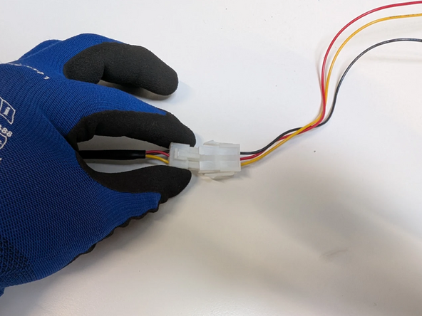
  3. Prepare the Mercedes Power Harness HRN-EE06K3 harness and connect the Molex connector with the yellow wire as shown
    • Prepare the Mercedes Power Harness HRN-EE06K3 harness and connect the Molex connector with the yellow wire as shown

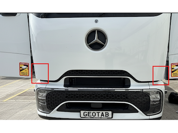
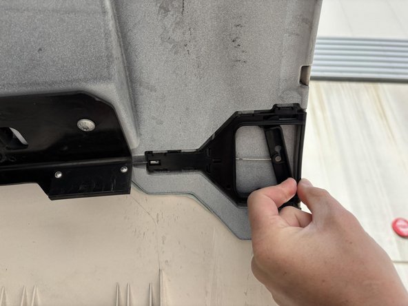
  4. Carefully open both sides of the truck's engine bay by moving the lever as illustrated in the provided photographs. Carefully open both sides of the truck's engine bay by moving the lever as illustrated in the provided photographs.
    • Carefully open both sides of the truck's engine bay by moving the lever as illustrated in the provided photographs.

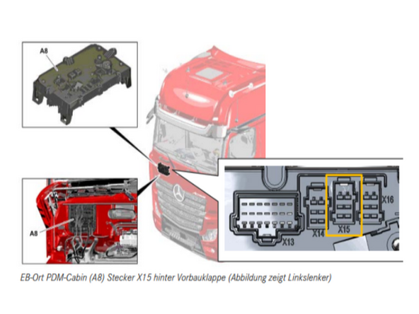
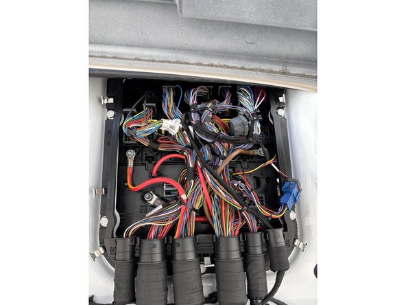
  5. Route the wires from the fuse area outside to the Bodybuilder interface, which is located in the engine bay.
    • Route the wires from the fuse area outside to the Bodybuilder interface, which is located in the engine bay.

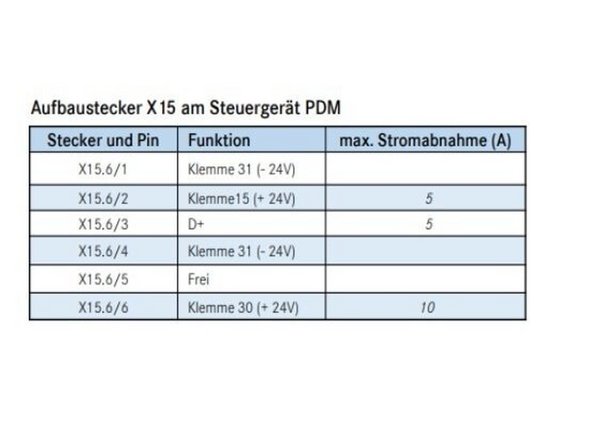
  6. Verify the X15 Power Sources Using a Multimeter in order to be on the safe side ! ⚡ Fuses are not required because power is drawn from an already fused location, as mentioned in step 5 regarding pin mapping.
    • Verify the X15 Power Sources Using a Multimeter in order to be on the safe side ! ⚡

    • Fuses are not required because power is drawn from an already fused location, as mentioned in step 5 regarding pin mapping.

    • Pinout Reminder !

    • - RED (live) Pin number 6

    • - YELLOW (ignition) wire Pin number 2

    • - BLACK (ground) wire Pin number 1

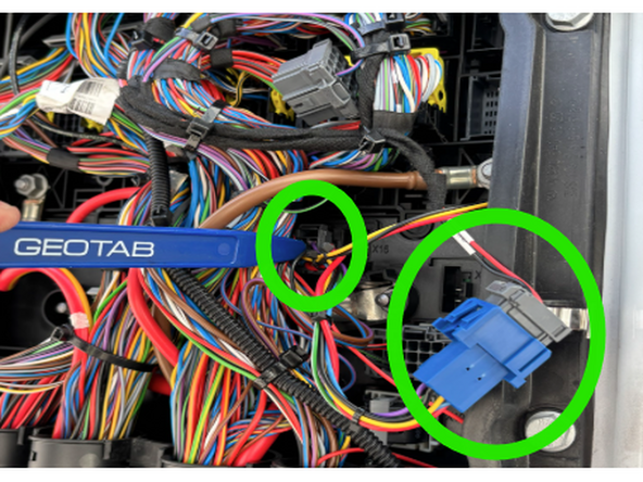
  7. Insert the connector into location X15. If X15 is already occupied by another connector, please disconnect it and attach it to the other end of our T-harness.
    • Insert the connector into location X15.

    • If X15 is already occupied by another connector, please disconnect it and attach it to the other end of our T-harness.

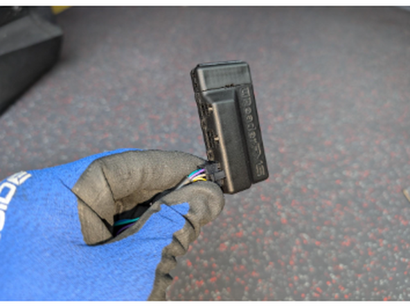
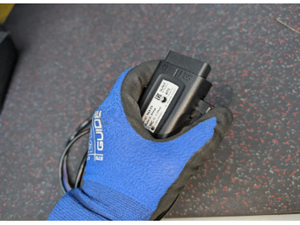
  8. Connect the Molex connector of the IOX-Null harness with the IOX-UREADER or IOX-CLAMP and with the Go device. Connect the Molex connector of the IOX-Null harness with the IOX-UREADER or IOX-CLAMP and with the Go device.
    • Connect the Molex connector of the IOX-Null harness with the IOX-UREADER or IOX-CLAMP and with the Go device.

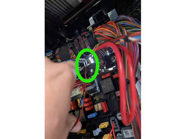
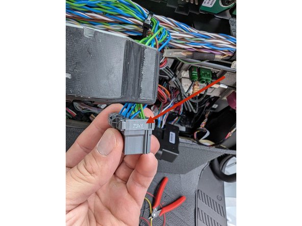
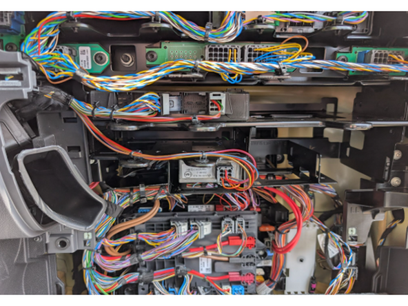
  9. Returning to the inside of the Truck’s interior, Locate the gray connector, labeled Z3X1, in the top center of the fuse panel. This connector has multiple twisted pairs of blue and green wires. Attach the UREADER or IOX-CLAMP to any of these blue and green wire pairs.
    • Returning to the inside of the Truck’s interior, Locate the gray connector, labeled Z3X1, in the top center of the fuse panel.

    • This connector has multiple twisted pairs of blue and green wires. Attach the UREADER or IOX-CLAMP to any of these blue and green wire pairs.

  10. Remove the top cover to access mounting location for GO device
    • Remove the top cover to access mounting location for GO device

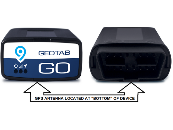
  11. The GPS-antenna is located at the underside of the Geotab device.
    • The GPS-antenna is located at the underside of the Geotab device.

    • ! IMPORTANT: Ensure when securing the device into the vehicle, that this side is facing away from any metal surfaces.

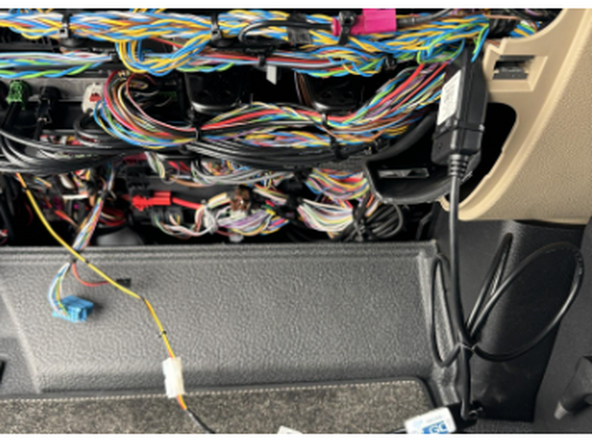
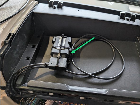
  12. If the vehicle has a solid surface on top of fuse box.  Ensure the surface is clean, and free of dust, oil etc. and attach the double sided tape of the back of our SPR-INSTALLBAG and stick it to the bracket. Apply firm pressure to it for at least 30 seconds to ensure the tape bonds correctly. Connect the other part of HRN-CW03K3 with the Go device and secure the connection of the IOX-CLAMP and the OBD interface with cable tie. Connect the white connectors of the HRN-CW03K3 with each other.
    • If the vehicle has a solid surface on top of fuse box. Ensure the surface is clean, and free of dust, oil etc. and attach the double sided tape of the back of our SPR-INSTALLBAG and stick it to the bracket. Apply firm pressure to it for at least 30 seconds to ensure the tape bonds correctly.

    • Connect the other part of HRN-CW03K3 with the Go device and secure the connection of the IOX-CLAMP and the OBD interface with cable tie.

    • Connect the white connectors of the HRN-CW03K3 with each other.

    • Use cable ties to secure loose wires to leave the space clean and close everything up.

  13. Cable tie the loose parts and wires to leave the space clean and close everything up.
    • Cable tie the loose parts and wires to leave the space clean and close everything up.

Finish Line

Jason Fox

Member since: 9/14/23

145 Guides authored

Team

Field Service Specialists Member of Field Service Specialists

8 Members

300 Guides authored