-
-
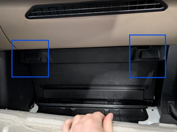
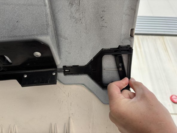
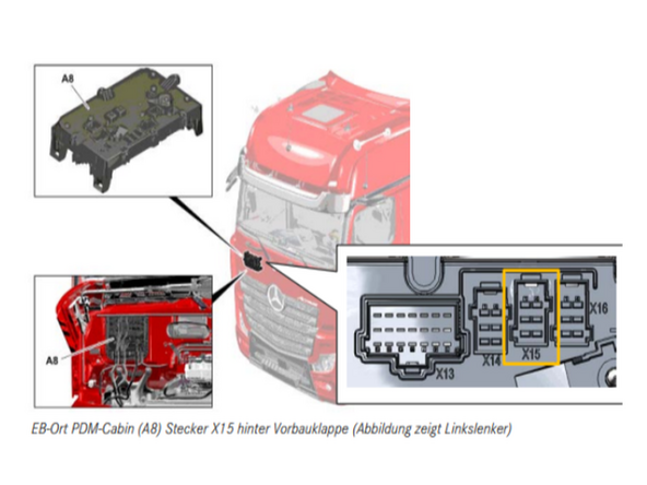
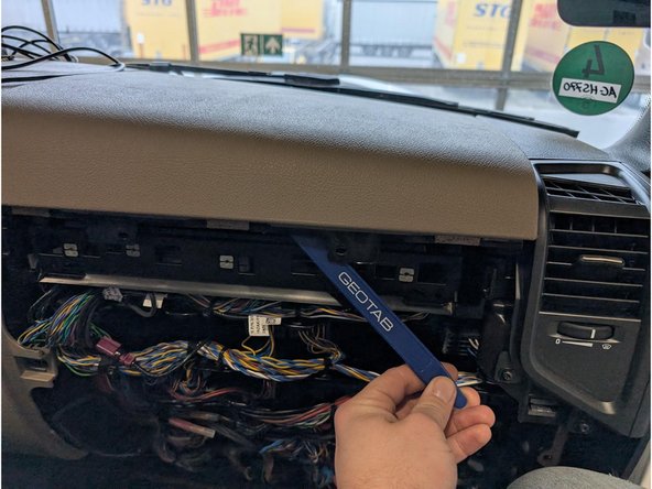
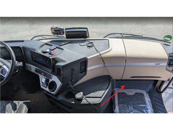
Access the fuse-panel located at the bottom of the dashboard in the passenger's footwell behind a plastic cover clearly labelled "OBD"
-
-
-
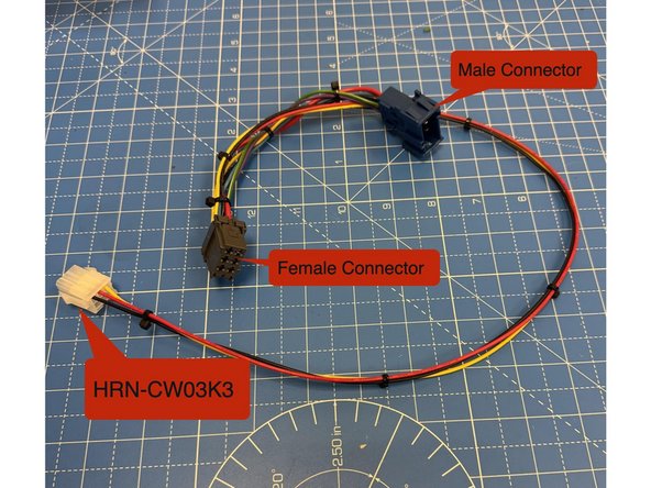
Using components sourced separately from above, Prepare the HRN-CW03K3 harness
-
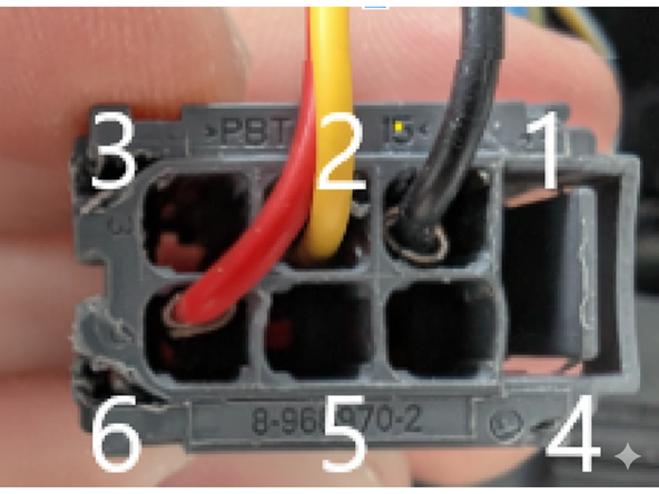
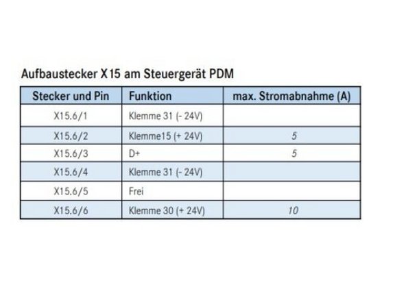
Using the Male and Female connectors with a short wire in between build the harness to as shown:
-
- RED (live) Pin 6
-
- YELLOW (ignition) wire Pin 2
-
- BLACK (ground) wire Pin 1
-
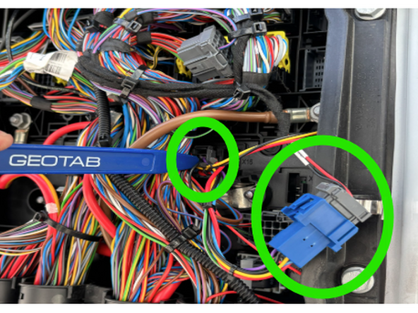
Insert pins A9909820826 into the female connector, ensuring each is connected to a corresponding wire as depicted in the photograph. Replicate this procedure with the male connector, utilizing male pins 1-962843-3. Fuses are not required as power is drawn from an already fused location.
-
-
-
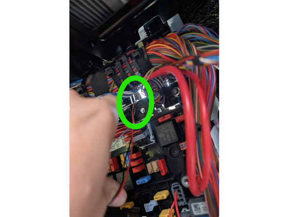
Verify the X15 Power Sources Using a Multimeter in order to be on the safe side ! ⚡
-
Fuses are not required because power is drawn from an already fused location, as mentioned in step 5 regarding pin mapping.
-
Pinout Reminder !
-
- RED (live) Pin number 6
-
- YELLOW (ignition) wire Pin number 2
-
- BLACK (ground) wire Pin number 1
-
-
-
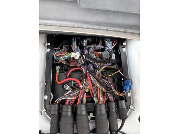
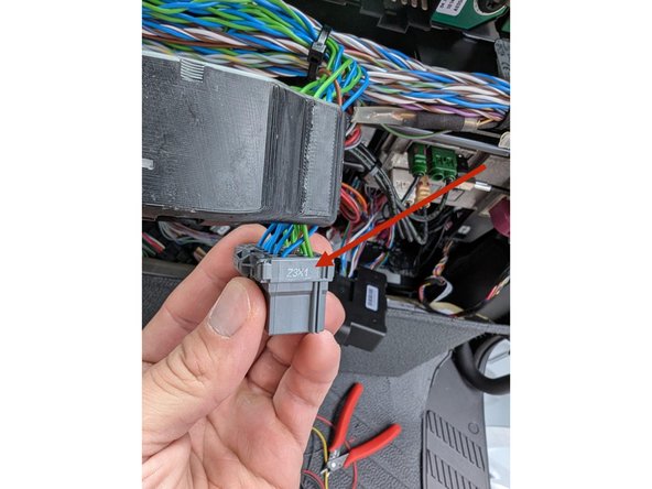
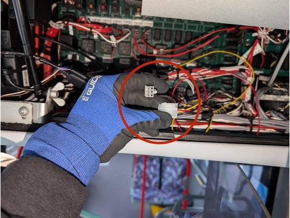
Returning to the inside of the Truck’s interior, Locate the gray connector, labeled Z3X1, in the top center of the fuse panel.
-
This connector has multiple twisted pairs of blue and green wires. Attach the IOX-CAN to any of these blue and green wire pairs.
-
-
-
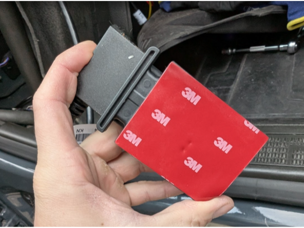
Ensure the surface is clean, and free of dust, oil etc. and attach the double sided tape of the back of our SPR-INSTALLBAG and stick it to the bracket. Apply firm pressure to it for at least 30 seconds to ensure the tape bonds correctly.
-
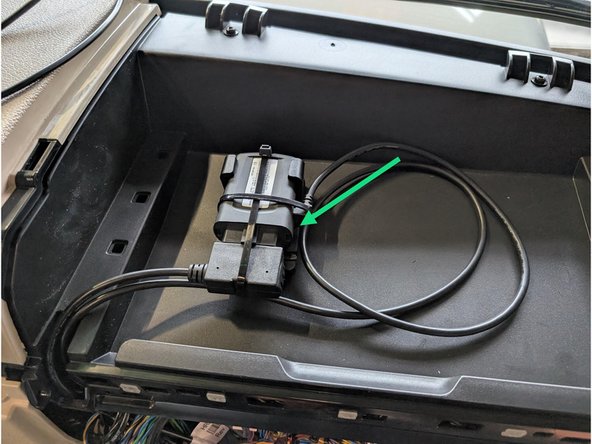
Connect the other part of HRN-CW03K3 with the Go device and secure the connection of the IOX-CAN and the OBD interface with cable tie.
-
Connect the white connectors of the HRN-CW03K3 with each other.
-
Use cable ties to secure loose wires to leave the space clean and close everything up.
-