
Recommended Tools & Consumables
-
-
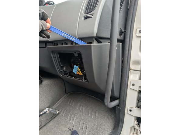
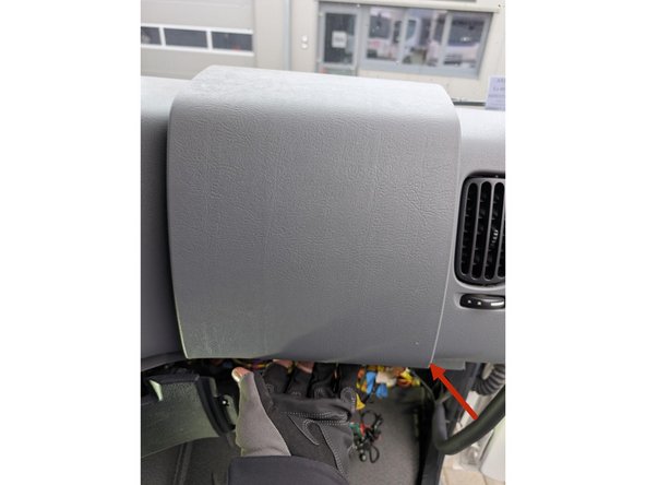
The fuse box is located on the passenger side.
-
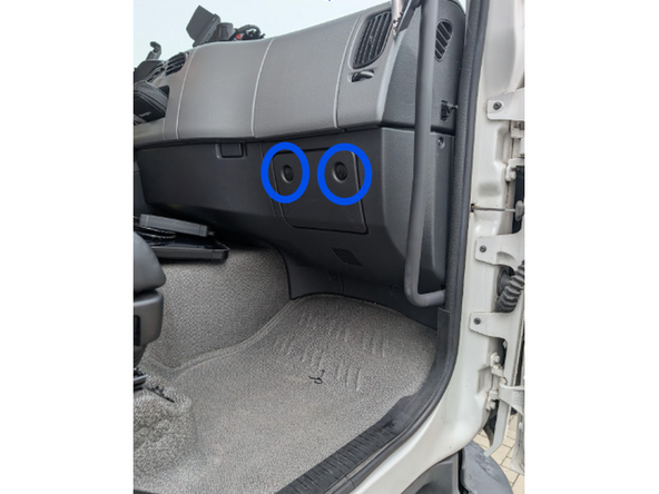
Unlock the cover with a flat screwdriver and set the cover aside.
-
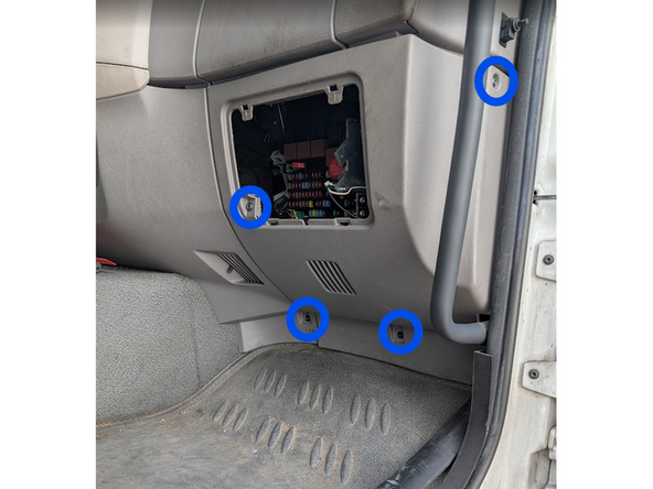
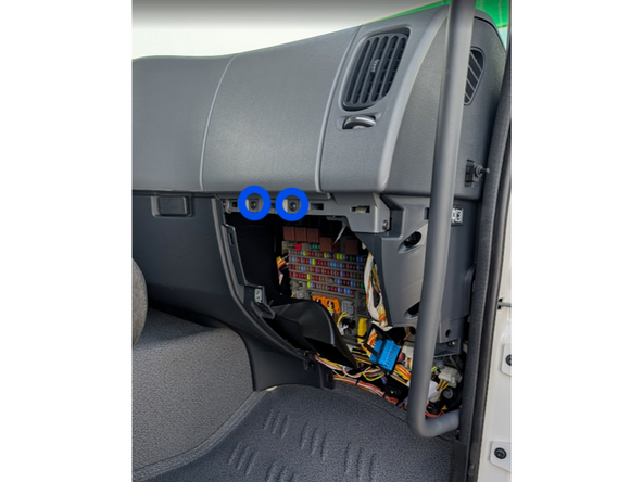
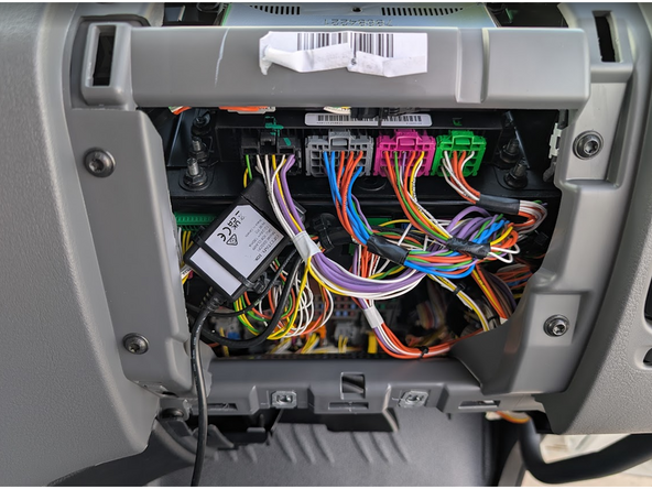
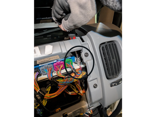
Remove the screws from the middle interior panel as shown.
-
-
-
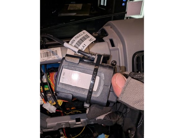
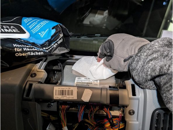
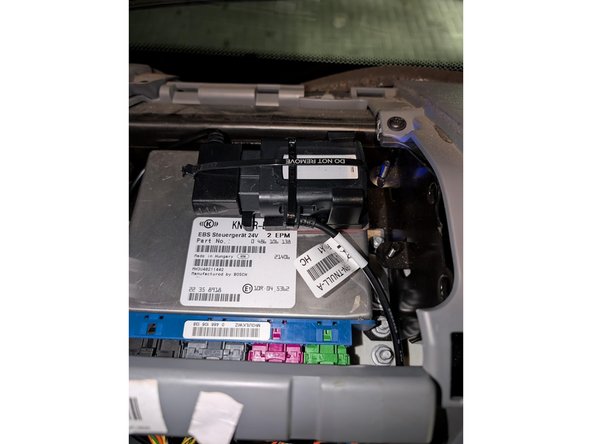
Clean the EBS ECU surface with an alcohol-based cleaning solution.
-
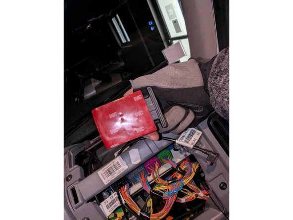
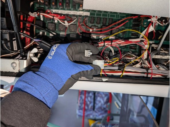
Apply the double-sided tape from the SPR-INSTALLBAG onto the mounting bracket and GO device.
-
Mount the SPR-INSTALLBAG firmly on the EBS ECU. Secure the GO device and HRN-CW03K3 harness connection with cable ties.
-
IMPORTANT: The GPS antenna is on the underside of the Geotab device. Ensure this side faces away from any metal surfaces when mounting.
-
Almost done!
Finish Line