Recommended Tools & Consumables
No Recommended Tools & Consumables specified.
Hardware & Accessories
-
-
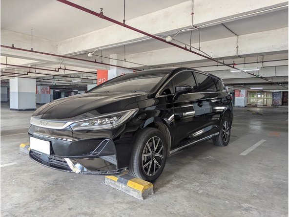
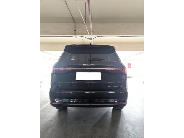
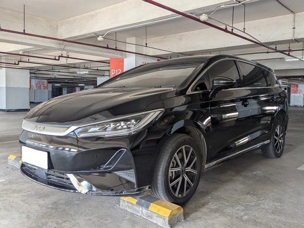
Take exterior photos of the vehicle from the front, side, and rear.
-
Identify the vehicle model (BYD M6 EV 2025+), equipment, and any relevant features.
-
-
-
Additional exterior photo showing vehicle features.
-
-
-
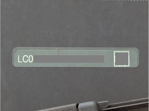
Photograph the VIN, chassis number, or serial number.
-
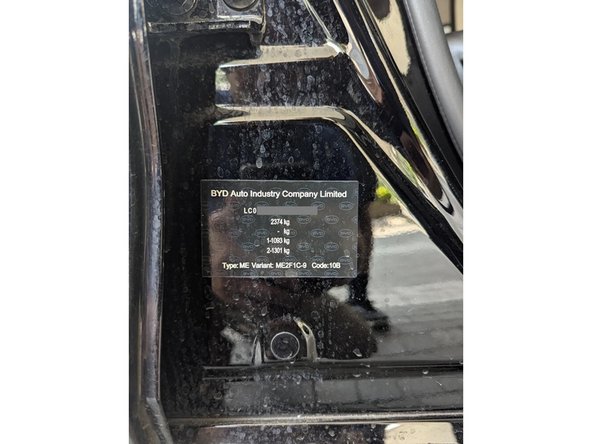
Take photos of any vehicle identification and build plates.
-
-
-
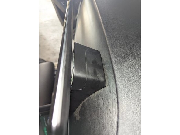
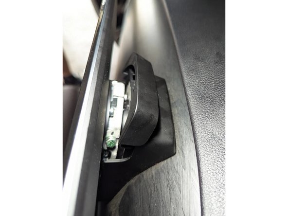
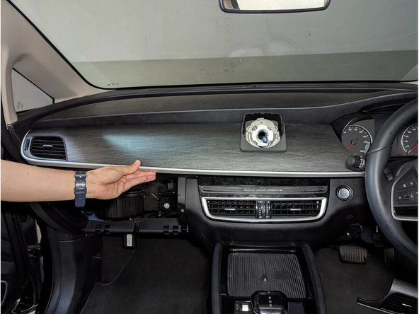
Just behind the infotainment display, remove the top cover using a flat-bladed screwdriver or plastic pry tool.
-
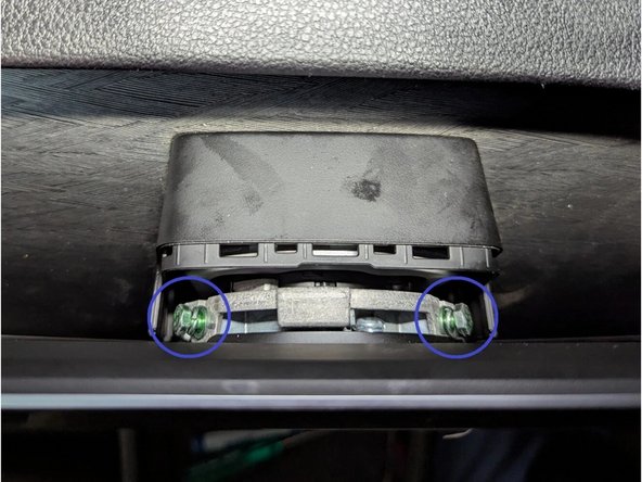
Remove the two Hex nuts using an 8mm spanner.
-
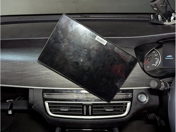
Rotate the infotainment display to detach it from the metal bracket.
-
-
-
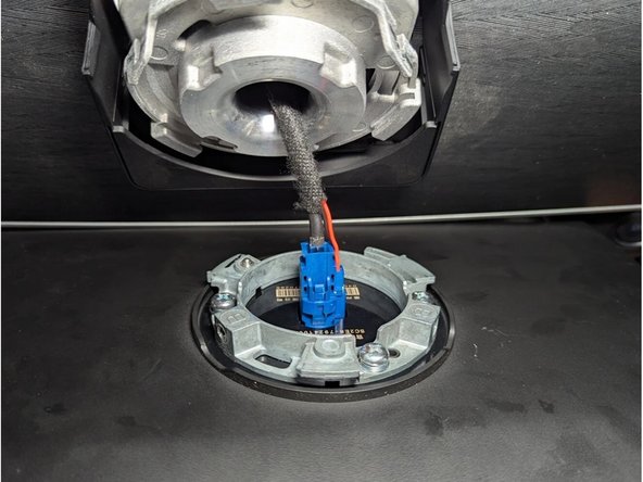
Unplug the blue connector to completely remove the infotainment display.
-
-
-
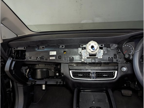
Remove the front panel using a flat-bladed screwdriver or plastic pry tool.
-
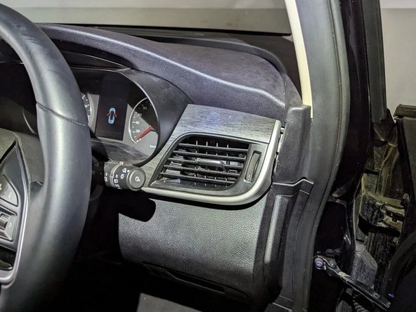
Remove the side air vent using a flat-bladed screwdriver or plastic pry tool.
-
-
-
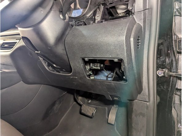
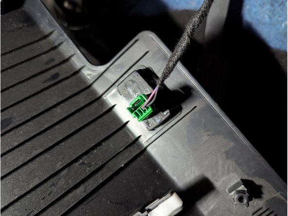
Remove the change box. Unclip the driver-side front panel held by plastic clips. Unplug the 4-pin green connector to completely remove it.
-
-
-
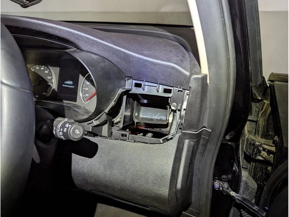
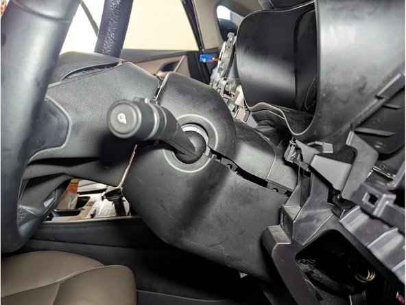
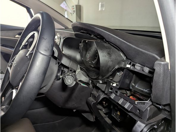
Unclip the steering column cover using a flat-bladed screwdriver or plastic pry tool.
-
Next, unclip the instrument cluster cover and remove the whole assembly.
-
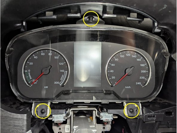
Remove the instrument cluster held by 3 screws as shown.
-
-
-
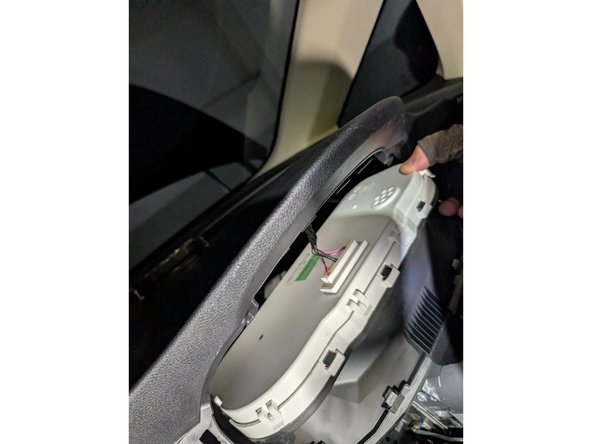
Pull it outwards and unplug the 40-pin white connector behind it to completely remove it.
-
-
-
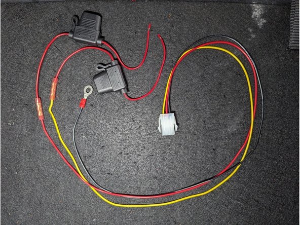
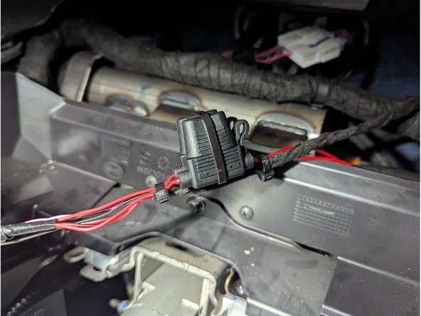
Prepare the HRN-CW03K3-A harness by using the supplied parts and fuse holders in the HRN-5AFUSEKIT.
-
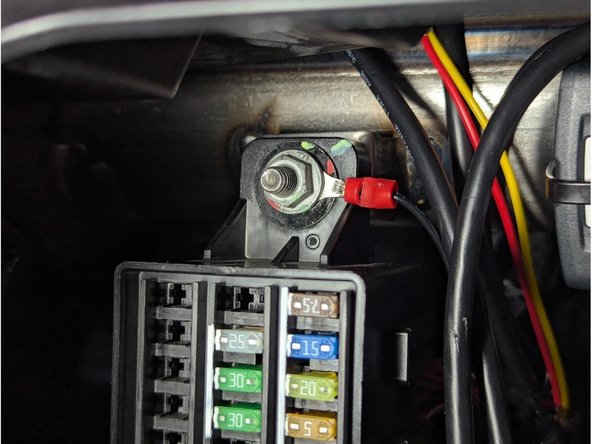
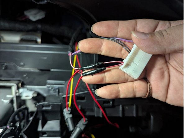
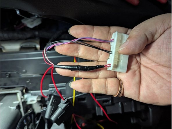
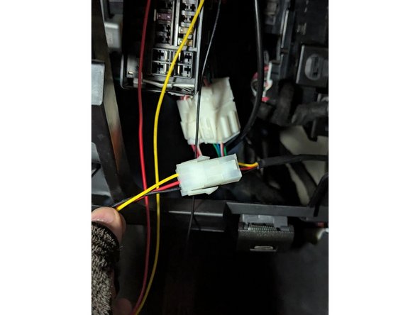
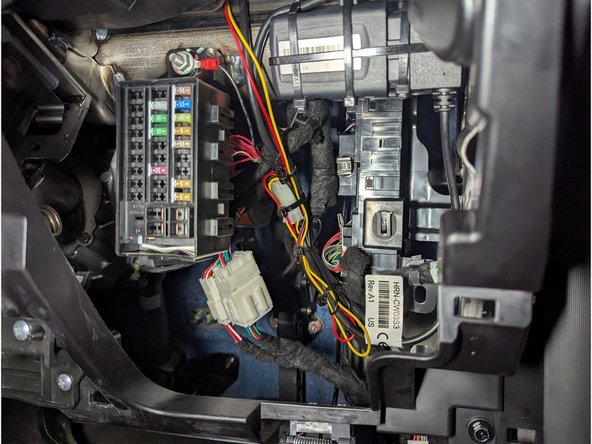
Route the white connector of the HRN-CW03K3-A harness from the top towards the fuse block. Attach the BLACK wire (GROUND) as shown.
-
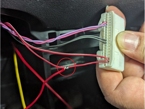
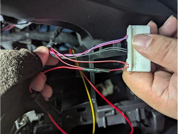
Strip a portion of the RED-BLACK wire (Pin 39) and connect the RED wire (POWER). Solder for a secure connection. Insulate with electrical tape.
-
-
-
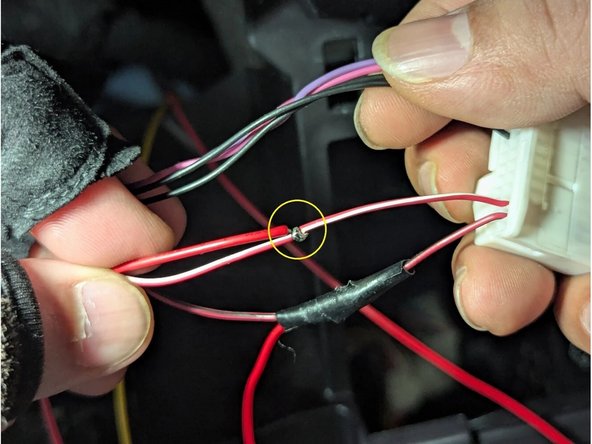
Strip a portion of the RED-WHITE wire (Pin 38) and connect the YELLOW wire (IGNITION). Solder for a secure connection. Insulate with electrical tape.
-
-
-
Secure the remaining length of the harness with cable ties as shown.
-
-
-
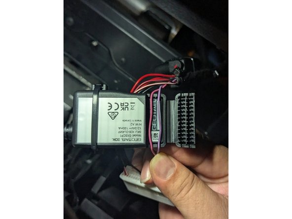
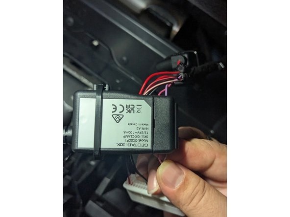
Open the clamp and insert both wires (Pin 4 = Pink and Pin 5 = Violet) into either of the device cavities. Ensure the wires are seated in the grooves of the clamp as shown.
-
Close the IOX-CLAMP and ensure it clips without pinching any wires. Secure the remaining IOX cable length with cable ties as shown.
-
-
-
Connect the IOX-CLAMP to the GO device. Refer to standard installation guide instructions for the connection procedure.
-
-
-
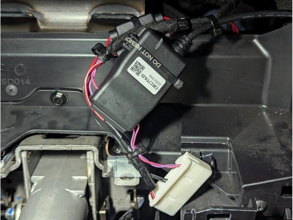
Plug the GO device into the HRN-CW03K3-A harness and secure it with a cable tie.
-
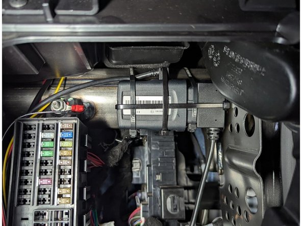
Secure the GO device to a suitable location using cable ties as shown. Ensure that the serial number faces outwards, and is not covered by or in contact with any metal surface.
-
-
-
Connect both ends of the white connector of the HRN-CW03K3-A harness.
-
-
-
Secure any spare or slack cabling neatly with cable ties.
-
Take a general area photo of the installation.
-
-
-
Replace all panels, connectors, screws, and clips in the reverse order they were removed.
-
Note all tools required and take a general area photo of the completed installation.
-