
Recommended Tools & Consumables
-
-
Open the cupholder.
-
Remove the (2) T-25 screws holding the fuse box cover in place.
-
Pull upward to remove the PDM cover.
-
-
-
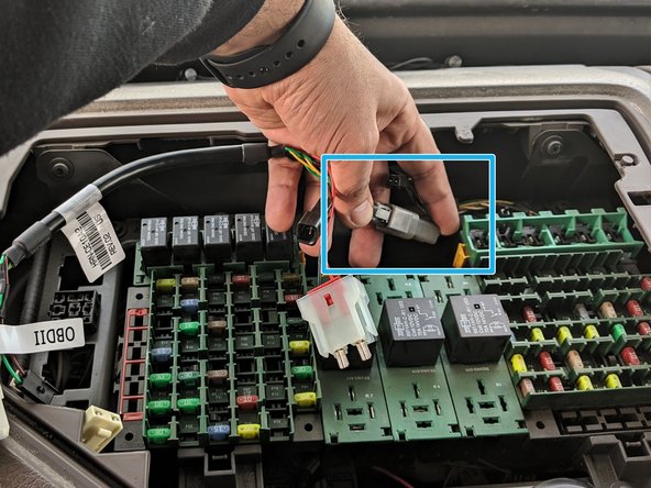
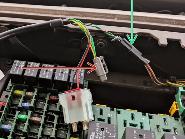
For 2004 - 2007 Volvo trucks where the gray 2-pin J1939 connector is not available:
-
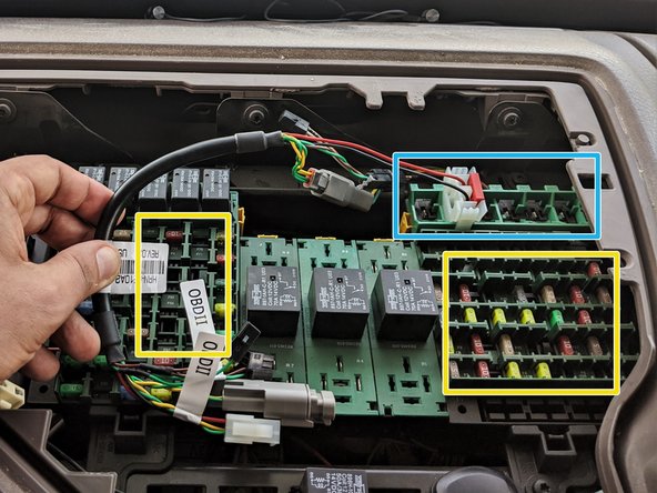
Plug the black 2-pin connector from the HRN-CE10K2 (green and brown wires) into the mating black 2-pin connector from the top passenger corner of the fuse box.
-
-
-
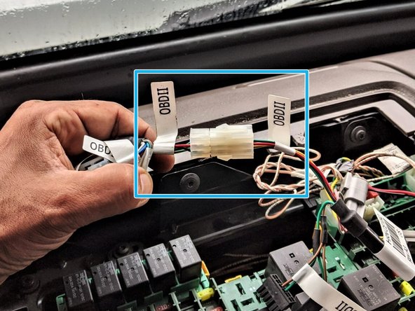
Connect the white 2-pin connector from the kit into any spare constant power slot.
-
Test & verify for +12V constant and Chassis Ground with a DMM prior to connection.
-
Some of these spare circuits are fed with ignition feed vs. battery, again verify using DMM.
-
Always use a Digital Multi Meter.
-
Battery feed circuits typically top row of terminals and chassis ground feed circuits typically bottom row of terminals.
-
Installation of a fuse into this circuit may be required.
-
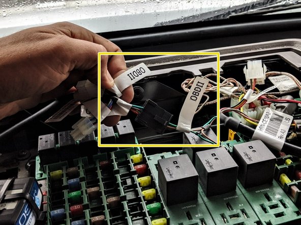
See PDM cover for reference.
-


Team

Authors: Field Service Install Member of Authors: Field Service Install
2 Members
10 Guides authored