
Recommended Tools & Consumables
-
-
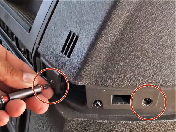
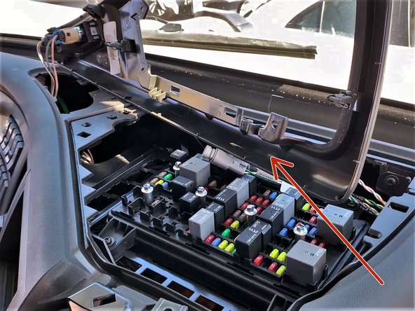
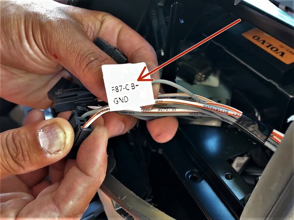
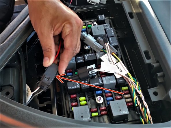
Remove the fuse box cover.
-
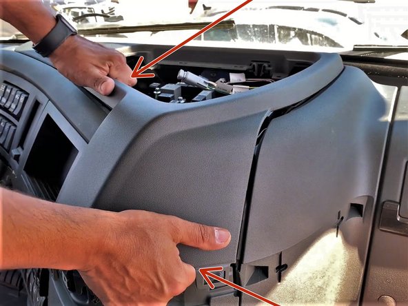
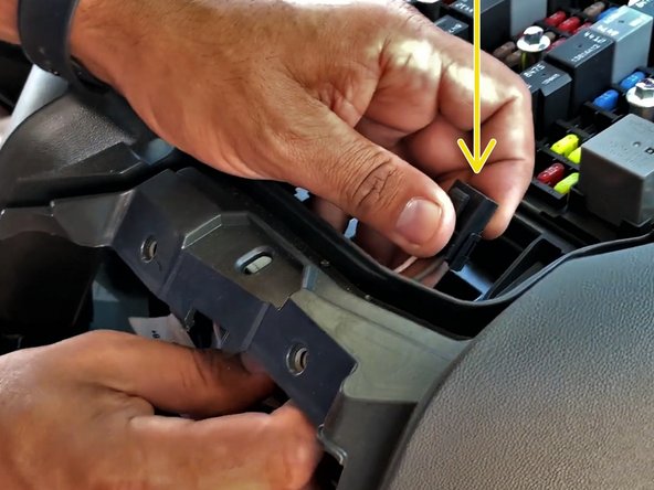
To remove carefully pull up from windshield side towards driver’s seat.
-
A plastic trim tool is recommended for this step.
-
When removing this cover, DO NOT PRY FROM THE FRONT! This panel has tabs that hook into the dash and will break.
-
-
-
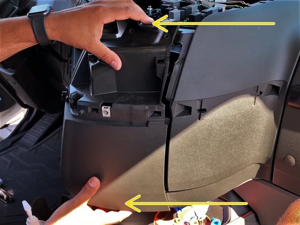
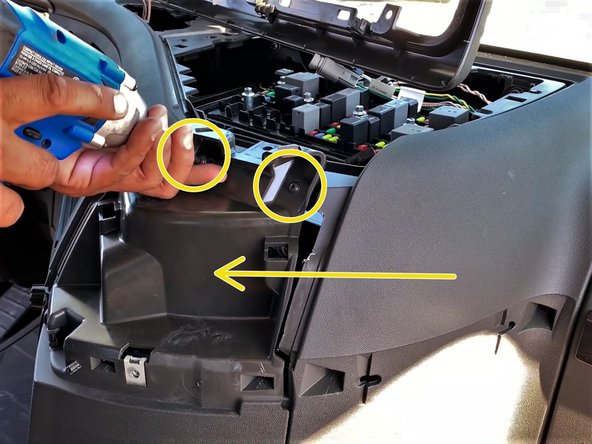
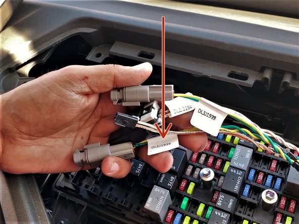
Remove the trim panel that wraps towards the passenger side.
-
Release this trim panel starting from the left side then pull/pry the trim straight towards you.
-
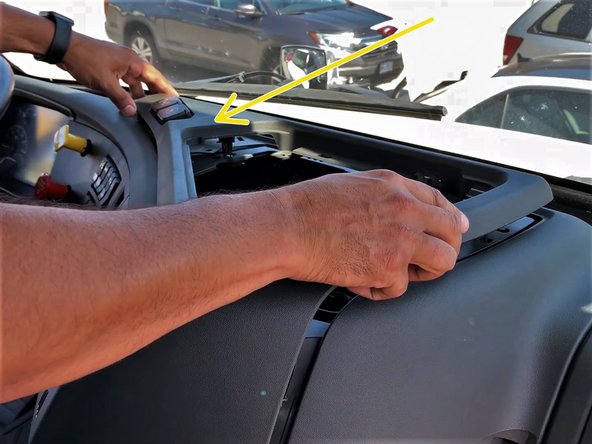
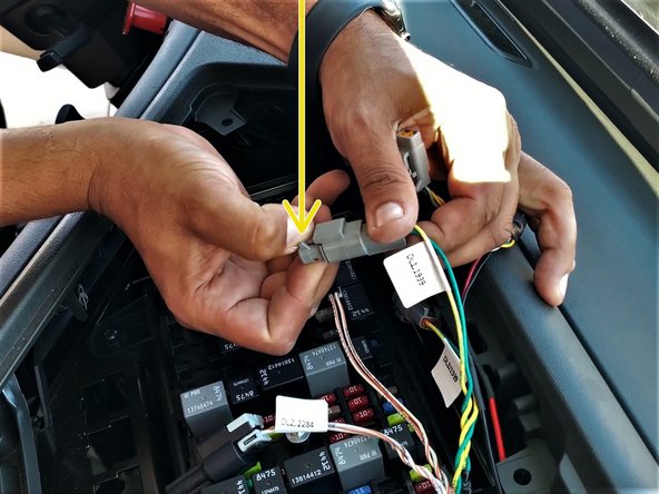
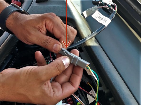
Remove the trim panel that wraps towards the drivers side.
-
Release this trim by prying at the clips straight out.
-
The end closest to the steering column slides out to the passenger side. DO NOT PRY to release, it will break!
-


Team

Authors: Field Service Install Member of Authors: Field Service Install
2 Members
10 Guides authored