Introduction
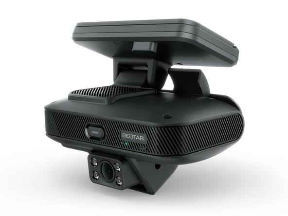
The GO Focus Pro is a dual-lens dashcam designed for fleets requiring advanced safety video telematics. It features road-facing and cabin-facing cameras with continuous AI inference for pre-collision warnings, red light detection, and pedestrian detection. The GO Focus Pro mounts to the windshield and connects to the vehicle via the HRN-IOXGFPRO-3W 3-wire harness, drawing ignition and constant power from the fuse panel.
When equipped with TVI auxiliary cameras, the GO Focus Pro provides full 360-degree video coverage around the vehicle, reducing blind spot incidents and enhancing driver awareness. All camera feeds are managed through the Geotab Video app and the Geotab fleet management platform.
Video Overview
-
-
Before installing the GO Focus Pro, download the Geotab Video app. Available on Apple App Store and Google Play Store.
-
Apple Geotab Video
-
Android Geotab Video
-
-
-
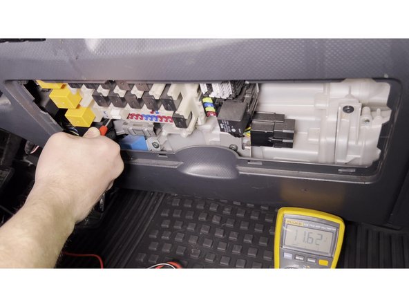
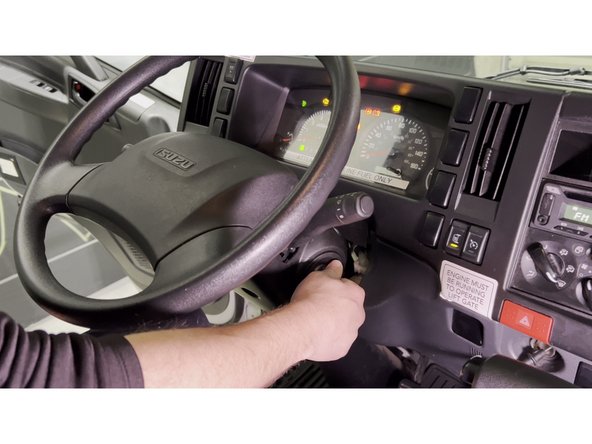
Using a multimeter, identify the constant battery power (B+) fuse slot and the ignition (ACC) fuse slot.
-
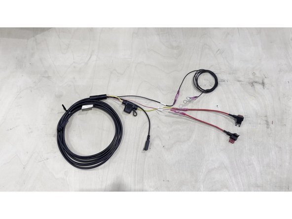
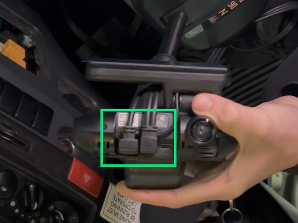
Temporarily connect the HRN-IOXGFPRO-3W 3-wire harness to the fusebox using fuse taps:
-
Red wire — ACC (ignition signal)
-
Yellow wire — Constant B+ (battery power)
-
Black wire — Ground (GND)
-
This temporary connection powers the camera for adjustment. The harness will be routed and secured permanently in a later step.
-
-
-
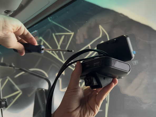
Pre-loosen the screws on the camera using the provided Allen key so you can adjust the camera angle.
-
Install the mounting bracket to the back of the device.
-
Connect the 3-wire harness cable to the GO Focus Pro.
-
-
-
Turn on the vehicle and wait for the LED on the GO Focus Pro to go solid green.
-
-
-
Launch the Geotab Video app.
-
Select "Activate dashcam" and follow the prompts on screen.
-
The app will ask you to scan the serial number located on the GO Focus Pro box.
-
-
-
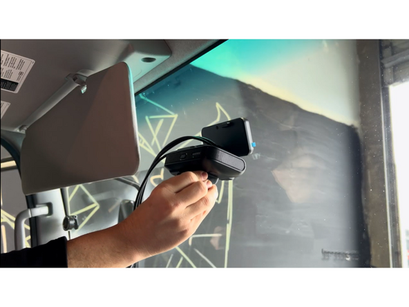
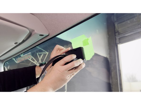
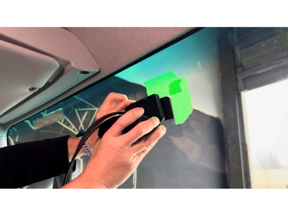
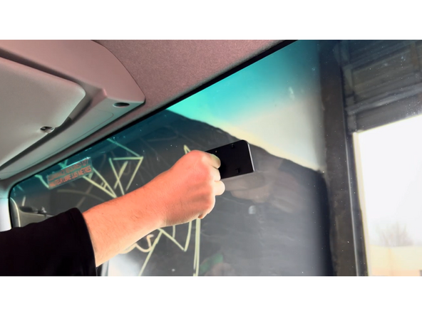
With the GO Focus Pro powered on and connected to the Geotab Video app, hold the camera in the desired mounting position on the windshield — within the wiper sweep area.
-
Use the app's live camera view to confirm the cabin and road camera angles look correct from this position.
-
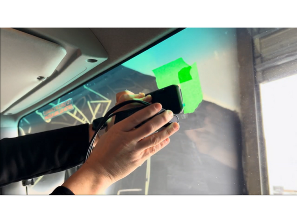
Once satisfied with the position, use masking tape to mark the perimeter of the mounting bracket on the windshield.
-
Verify sun visor does not block cabin facing camera when in the down positon.
-
-
-
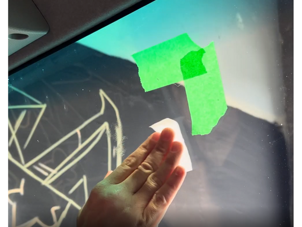
Use the provided alcohol wipe to thoroughly clean the mounting area on the windshield. Let the alcohol evaporate completely before proceeding.
-
Do not touch the cleaned area with bare hands — skin oils will reduce adhesion.
-
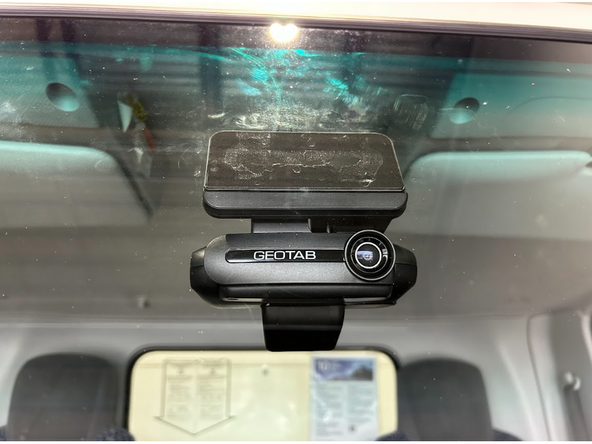
Remove the adhesive backing from the mounting bracket on the back of the camera.
-
Press the camera firmly onto the cleaned area of the windshield and hold with steady pressure for 30 seconds.
-
If the windshield is below 50°F (10°C), use the vehicle's defrost to warm the glass before mounting — cold glass significantly reduces adhesive bond strength.
-
-
-
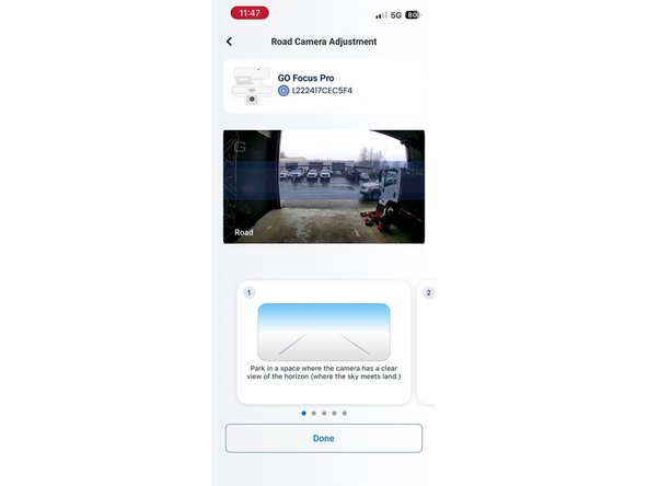
Select "Adjust" for the road-facing camera.
-
Adjust the camera so that the horizon is in the blue box.
-
-
-
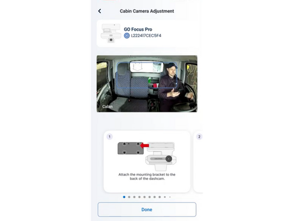
In the app, select "Adjust" in the cabin section.
-
Adjust the physical camera so that the driver's head is sitting in the blue box.
-
Sit in a normal driving position when adjusting the cabin camera to ensure proper alignment.
-
-
-
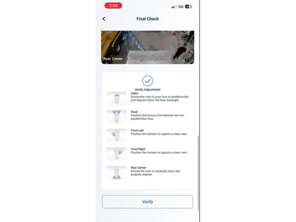
Once both camera angles are set, the app will ask you to verify and do a final check.
-
Select "Verify" and the verification is complete.
-
-
-
Dismount the camera from the mounting bracket.
-
Press the mounting bracket for an additional 30 seconds to ensure it is firmly in place.
-
Place the camera back on the mounting bracket.
-
-
-
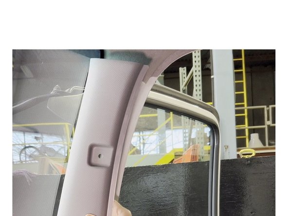
Carefully remove the cover for the driver's side A-pillar and any additional paneling required to route the harness.
-
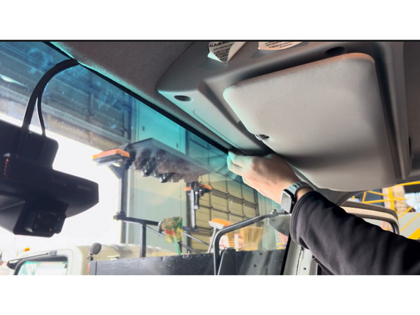
Tuck the harness cable behind the headliner toward the A-pillar, ensuring it is not obstructing the driver's view.
-
Secure the cable along the A-pillar in a way that it does not obstruct the airbag functionality.
-
Use cable ties as required. Trim any excess tie.
-
-
-
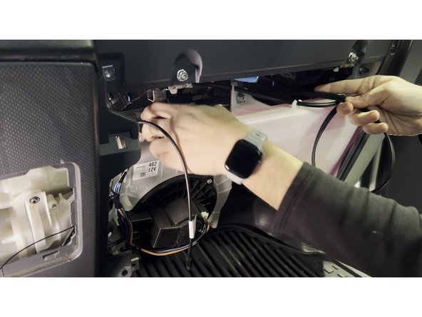
Route the harness cable from behind the headliner down to the fusebox.
-
Make the permanent fuse tap connections — Red (ACC), Yellow (B+), Black (GND).
-
Secure all wiring neatly behind the fusebox panel using cable ties. Trim any excess tie.
-
-
-
All in-vehicle devices and related cabling must be securely fastened and kept clear of all vehicle controls, airbags, and gas, brake and clutch pedals.
-
This requires the use of a cable tie when securing the device or any extension harness to the OBD connector, securing both sides of the harness. If you do not use a cable tie, vibration in the vehicle can lead to a loose connection which could cause the vehicle’s engine computer to fail, causing potential loss of vehicle control and serious injury.
-
Inspect devices and cabling regularly to ensure all devices and cabling continue to be securely attached.
-
If at any point after an in-vehicle device is installed a warning light illuminates on the vehicle dash or the vehicle stalls or has a marked drop in performance, shut off the engine, remove the device, and contact your reseller. Continuing to operate a vehicle with these symptoms can cause loss of vehicle control, and serious injury.
-
-
-
Navigate to one of the following:
-
-
-
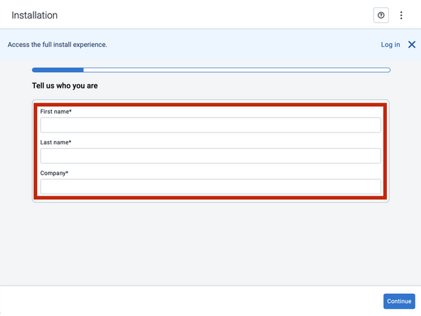
Note that the following steps are for the public version of MyInstall.
-
If you have an installer MyAdmin account, use this link
-
This link is also accessible via the MyInstall Public page.
-
-
-
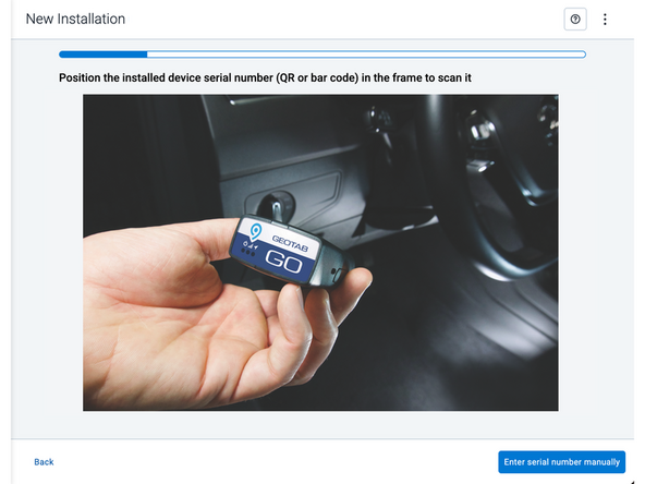
Two options are available to enter the device serial number:
-
Scan the device serial number (QR or barcode) using your mobile device.
-
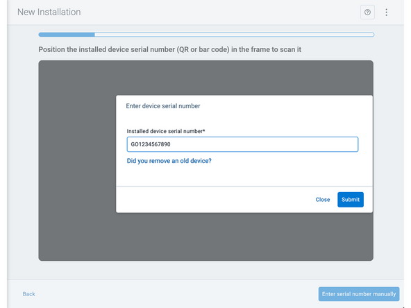
Press Enter serial number manually, enter the serial number, and then press Submit.
-
If you are also removing an old device, press Did you remove an old device? and then enter the removed device serial number.
-
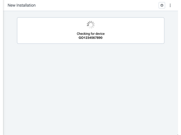
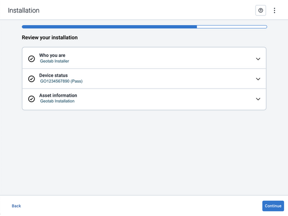
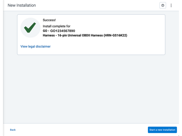
MyInstall takes a moment to check the device status.
-
-
-
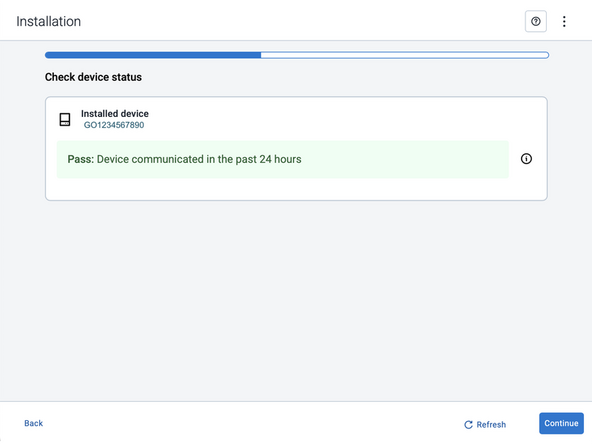
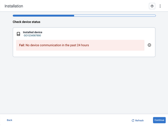
Installed device
-
Pass – The device has successfully communicated with the network in the last 24 hours.
-
Fail – The device has not communicated with the network in the last 24 hours.
-
If the device status shows as FAILED, verify the LED status and turn the ignition / engine off and on again.
-
Press Refresh to check the status again.
-
Refer to the MyInstall User Guide for detailed instructions.
-
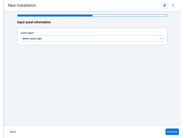
-
-
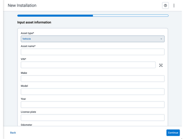
Asset name — Enter the vehicle or asset name. This field is mandatory.
-
VIN — Scan or enter the vehicle identification number (VIN). For scanning, select the scan icon [O] beside the field. This field is mandatory.
-
Make, Model, and Year — This information will be auto populated when you scan or enter a valid VIN. If it is not autopopulated, enter the information manually. NOTE: For some vehicle makes and models, the autopopulate option might not be possible.
-
License plate — Enter the vehicle license plate.
-
Odometer — Enter the vehicle odometer, and select the measurement unit (km or miles).
-
Engine hours — Enter the vehicle engine hours.
-
Camera ID (GO device only) — Scan or enter the installed camera identification (ID) number. NOTE: Depending on the camera type, the camera ID number can also be the camera’s International Mobile Equipment Identity (IMEI), or serial number. Select the information icon ⓘ to learn more about your camera’s ID number.
-
Work order reference — If applicable, enter a work reference number that is associated with the installation.
-
-
-
For the latest version of the Limitations of Use
-
Your in-vehicle devices must be kept clear of debris, water and other environmental contaminants. Failure to do so may result in units malfunctioning or short-circuiting, which can lead to a fire hazard and cause loss or serious injury.
-
This product does not contain any user-serviceable parts. Configuration, servicing, and repairs must only be made by an authorized reseller or installer. Unauthorized servicing of these products will void your product warranty.
-
The simplified EU declaration of conformity referred to in Article 10(9) shall be provided as follows:
-
Hereby, Geotab (Address: 2440 Winston Park Drive, Oakville, Ontario L6H 7V2, Canada, Phone number: 1 (877) 436-8221) declares that the radio equipment type ‘telematics device’ is in compliance with Directive 2014/53/EU. The full text of the EU declaration of conformity is available here.
-
WARNING: Cancer and Reproductive Harm
-