Introduction
Installation guide for the GO Anywhere Plus using the HRN-GA23WIRE harness.
Recommended Tools & Consumables
Hardware & Accessories
-
-
Do not attempt to install, reconfigure or remove any product from an asset while the asset is in motion or otherwise in operation. All installation, configuration or removal must be done only in stationary assets which are securely parked.
-
Attempting to service devices while the asset is in motion could result in malfunctions or accidents, leading to death or serious personal injury.
-
Keep devices clear of debris, water, and controls.
-
-
-
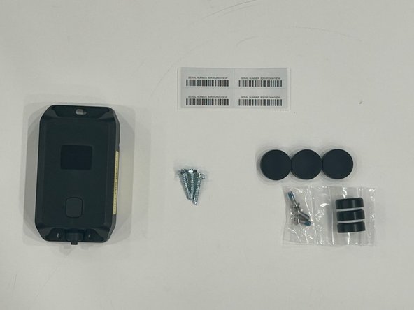
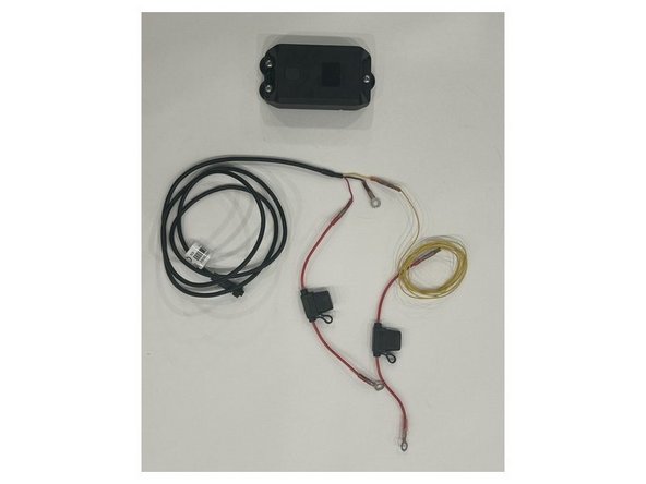
Review what is included before starting:
-
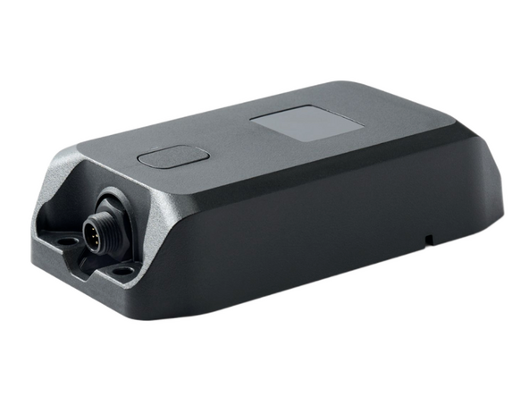
GO Anywhere Plus unit
-
Self-tapping screws
-
Serial number sticker for the device
-
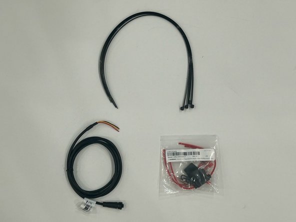
HRN-GA23WIRE harness
-
HRN-5AFUSEKIT
-
Cable ties
-
(ACC-GAMAG) Optional magnets with rubber covers (NOTE: Must be ordered separately)
-
-
-
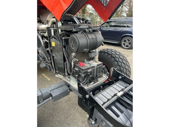
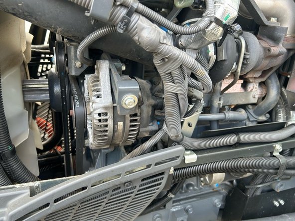
Find a suitable location with a solid mounting surface.
-
The GO Anywhere Plus must have optimal line of sight to the sky with no metal obstructions.
-
Ensure the surface has solid backing so screws hold the device securely.
-
OPTIONAL: Magnetic mounts (ACC-GAMAG) can be used for mounting instead of screws where applicable.
-
-
-
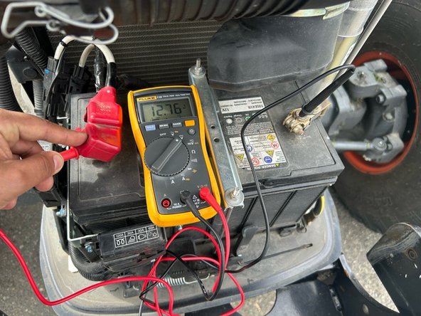
Verify the following power sources before connecting:
-
Locate and verify a constant +12/24V Battery source.
-
A suitable battery source will have +12/24V at all times, just like if you were to be connected directly to the battery.
-
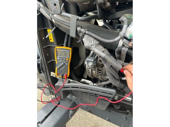
Locate and verify a +12/24V Ignition source.
-
A suitable Ignition source will have +12/24V while the key or button is set to on/run and 0V when set to off.
-
Always use a Digital MultiMeter.
-
-
-
Using the supplied HRN-5AFUSEKIT, prepare HRN-GA23WIRE harness as needed.
-
Wires can be extended as needed to reach power source. Always fuse within 3 inches of power connection interface.
-
-
-
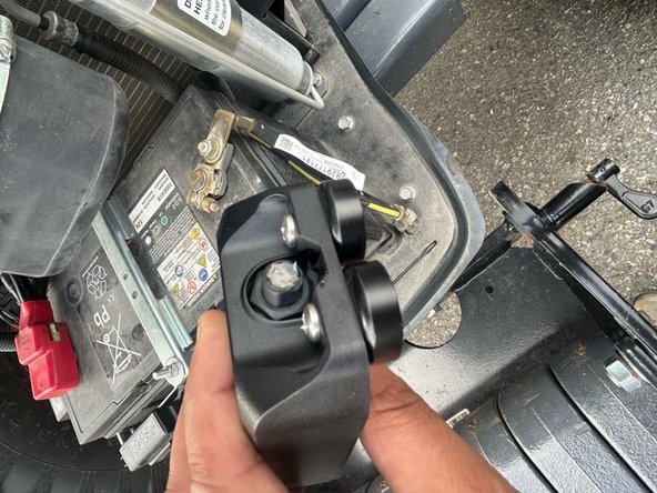
Remove the protective cap from the bottom of the GO Anywhere Plus device. Apply dielectric grease in connector when unit is exposed to the external elements.
-
Connect the female connector on the HRN-GA23WIRE harness to the GO Anywhere Plus device. Secure until snug, then tighten a further 1/4 turn.
-
Note that the connector is keyed to ensure correct orientation.
-
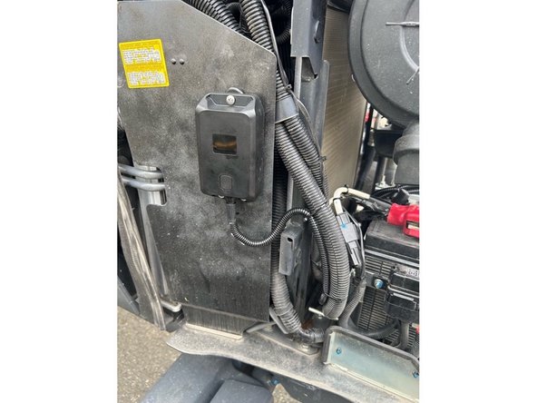
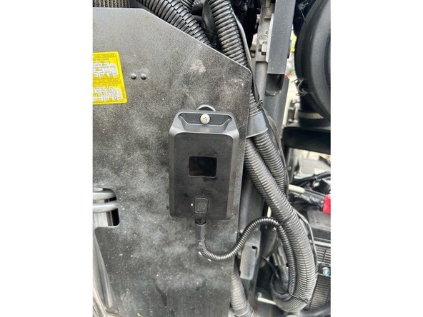
Mount the GO Anywhere using screws or magnetic mounts.
-
Route and protect wires with loom when exposed to external elements.
-
Before drilling, check behind the mounting location to ensure the area is clear of obstructions or electrical wires.
-
The GO Anywhere must be mounted solid to the asset.
-
When required use the appropriate grommet to prevent wire chafing.
-
-
-
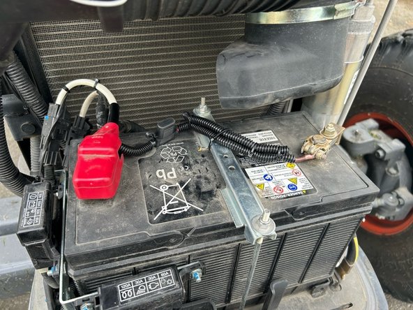
Complete all power connections as required for the application:
-
Red → Constant 12/24V
-
Yellow → 12/24V ignition
-
The Constant and Ignition connections must be protected by fuses.
-
The inline fuse holders should be located within 6 inches of the connection point.
-
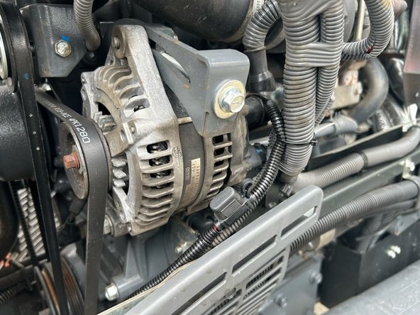
Either key cylinder or alternator ignition are acceptable methods to source ignition. (Alternator is considered true idle/run time).
-
Black → Ground
-
-
-
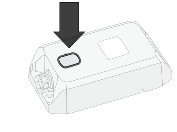
Turn on the ignition & press the button on the GO Anywhere Plus device.
-
For optimal performance, activate the device in an area with good cellular coverage and a clear view of the sky for GNSS/GPS.
-
LED state - WHITE - Slow Flash
-
Status - Activation in progress.
-
Action - Do not unplug or touch the device.
-
LED state - GREEN - Fast flash for 15 seconds
-
Status - Device is battery-only, or wired and ignition is not detected.
-
Action - No action required.
-
-
-
Solid Green LED indicates that the device is working properly and is detecting Ignition.
-
Proceed to Verify Installation.
-
Flashing Green LED indicates that the device is not detecting ignition.
-
Check the Ignition source / connection and repeat the activation steps.
-
-
-
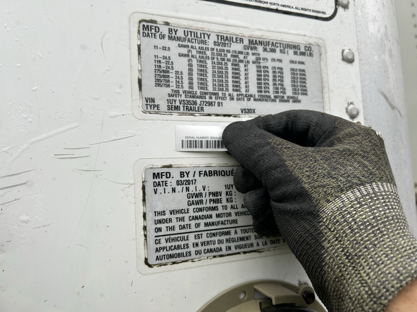
Re-assemble asset and place sticker in a suitable position.
-
-
-
All in-vehicle devices and related cabling must be securely fastened and kept clear of all vehicle controls, airbags, and gas, brake and clutch pedals.
-
This requires the use of a cable tie when securing the device or any extension harness to the OBD connector, securing both sides of the harness. If you do not use a cable tie, vibration in the vehicle can lead to a loose connection which could cause the vehicle’s engine computer to fail, causing potential loss of vehicle control and serious injury.
-
Inspect devices and cabling regularly to ensure all devices and cabling continue to be securely attached.
-
If at any point after an in-vehicle device is installed a warning light illuminates on the vehicle dash or the vehicle stalls or has a marked drop in performance, shut off the engine, remove the device, and contact your reseller. Continuing to operate a vehicle with these symptoms can cause loss of vehicle control, and serious injury.
-
-
-
Navigate to one of the following:
-
-
-
Note that the following steps are for the public version of MyInstall.
-
If you have an installer MyAdmin account, use this link
-
This link is also accessible via the MyInstall Public page.
-
-
-
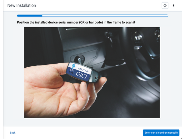
Two options are available to enter the device serial number:
-
Scan the device serial number (QR or barcode) using your mobile device.
-
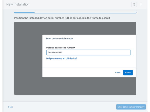
Press Enter serial number manually, enter the serial number, and then press Submit.
-
If you are also removing an old device, press Did you remove an old device? and then enter the removed device serial number.
-
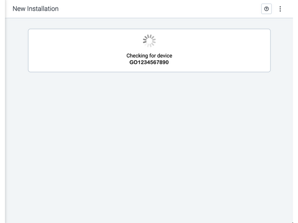
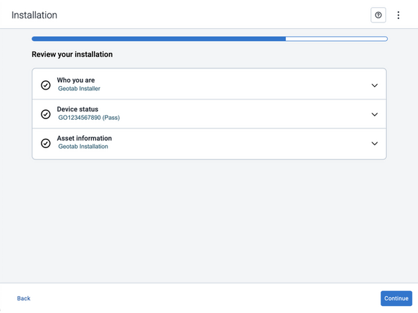
MyInstall takes a moment to check the device status.
-
-
-
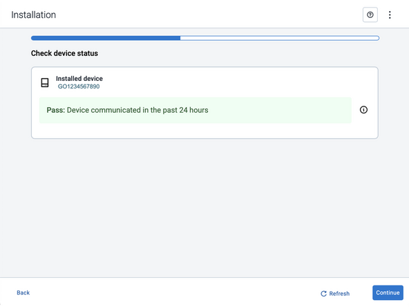
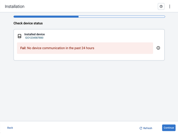
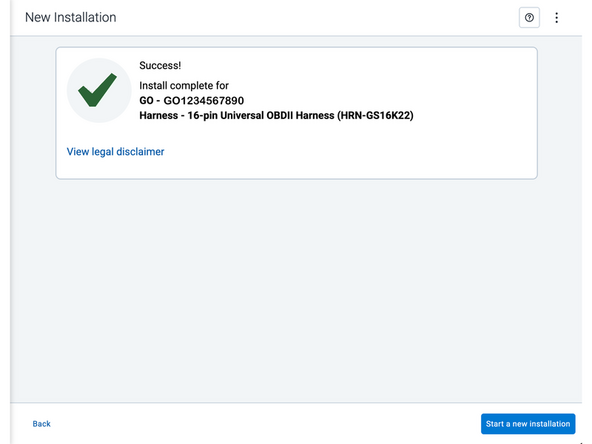
Installed device
-
Pass – The device has successfully communicated with the network in the last 24 hours.
-
Fail – The device has not communicated with the network in the last 24 hours.
-
If the device status shows as FAILED, verify the LED status and turn the ignition / engine off and on again.
-
Press Refresh to check the status again.
-
Refer to the MyInstall User Guide for detailed instructions.
-
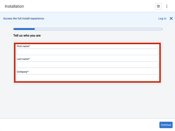
-
-
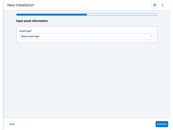
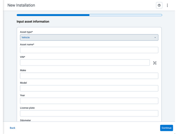
Asset name — Enter the vehicle or asset name. This field is mandatory.
-
VIN — Scan or enter the vehicle identification number (VIN). For scanning, select the scan icon [O] beside the field. This field is mandatory.
-
Make, Model, and Year — This information will be auto populated when you scan or enter a valid VIN. If it is not autopopulated, enter the information manually. NOTE: For some vehicle makes and models, the autopopulate option might not be possible.
-
License plate — Enter the vehicle license plate.
-
Odometer — Enter the vehicle odometer, and select the measurement unit (km or miles).
-
Engine hours — Enter the vehicle engine hours.
-
Camera ID (GO device only) — Scan or enter the installed camera identification (ID) number. NOTE: Depending on the camera type, the camera ID number can also be the camera’s International Mobile Equipment Identity (IMEI), or serial number. Select the information icon ⓘ to learn more about your camera’s ID number.
-
Work order reference — If applicable, enter a work reference number that is associated with the installation.
-
-
-
For the latest version of the Limitations of Use
-
Your in-vehicle devices must be kept clear of debris, water and other environmental contaminants. Failure to do so may result in units malfunctioning or short-circuiting, which can lead to a fire hazard and cause loss or serious injury.
-
This product does not contain any user-serviceable parts. Configuration, servicing, and repairs must only be made by an authorized reseller or installer. Unauthorized servicing of these products will void your product warranty.
-
The simplified EU declaration of conformity referred to in Article 10(9) shall be provided as follows:
-
Hereby, Geotab (Address: 2440 Winston Park Drive, Oakville, Ontario L6H 7V2, Canada, Phone number: 1 (877) 436-8221) declares that the radio equipment type ‘telematics device’ is in compliance with Directive 2014/53/EU. The full text of the EU declaration of conformity is available here.
-
WARNING: Cancer and Reproductive Harm
-


Team
