Recommended Tools & Consumables
Hardware & Accessories
No Hardware & Accessories specified.
-
-
This guide wiill walk you through Standard Installation using HRN-RCCCAAPX AND Non-standard installation (trailer unit on rigid truck) using HRN-CCCAAPX
-
-
-
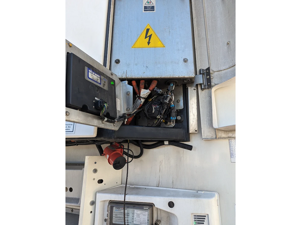
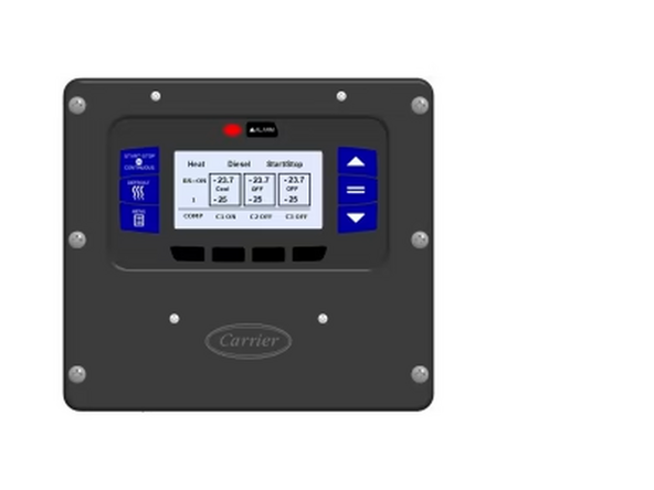
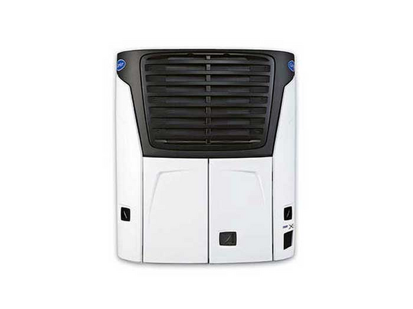
Locate the unit’s HMI and access to its rear part.
-
Unplug the unit original harness from the HMI.
-
-
-
Once the HRN-RCCCAAPX routing and all connections between the IOX-COLD RUGGED and the GO9 RUGGED are completed, follow steps 4 and onward in the IOX-COLD RUGGED Quick Start Guide .
-
Do not forget to fasten all the installed cables to the refrigeration unit harnesses and stationary mechanical parts of the asset to secure the cable management.
-
! IMPORTANT: The GO9 RUGGED must be powered by the three loose wires located on harness HRN-RCCTKSR2. For more details, refer to the quick start guide linked above.
-
! IMPORTANT: It is mandatory for every installation to use the MyInstall tool (requires a provisioned MyAdmin account) to configure the installation. If you do not do this, the device may not transmit the correct data.
-
You need a secure MyAdmin login to use this tool. If you do not have one, refer to the Creating MyInstall Credentials section of the MyInstall user guide.
-
-
-
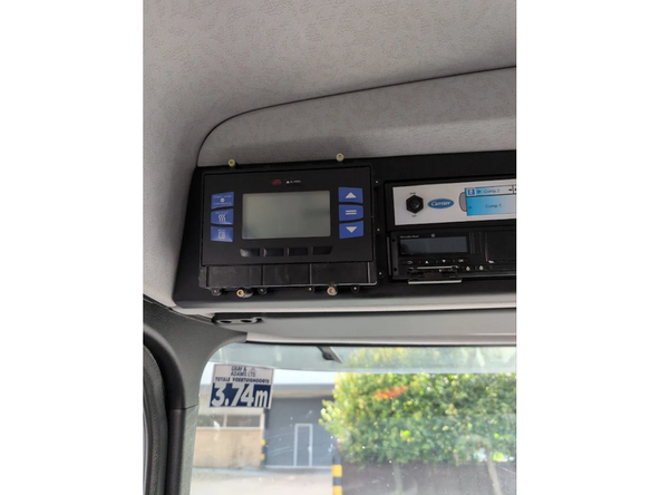
In certain cases, customers may have trailer refrigeration units fitted onto rigid trucks. The main HMI or remote panel is typically installed inside the cabin.
-
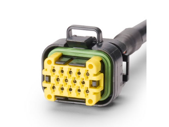
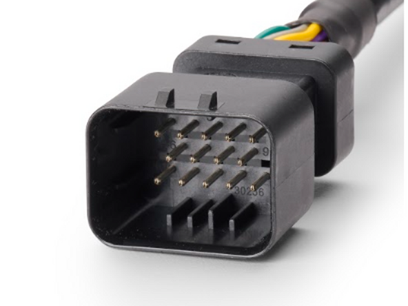
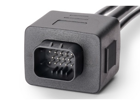
Pre-installation: Modify the HRN-CCCAAPX harness by cutting it close to the connectors to create a single harness from the IOX-COLD Molex connector to the APX controller.
-
-
-
Modify the HRN-CCCAAPX harness by cutting it close to the connectors to create a single harness from the IOX-COLD Molex connector to the APX controller.
-
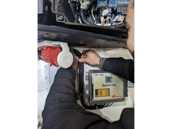
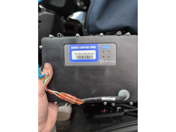
Unmount it from its location to access its wiring.
-
-
-
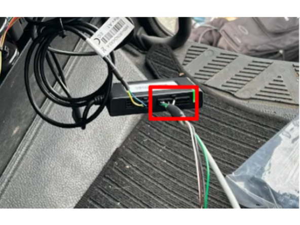
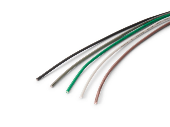
For most non-standard installation scenarios, the panel is connected to four or more wires. In this step, you’ll need to identify 3 wires: ground, CAN high, and CAN low using a Digital Multi Meter and the igntion must be ON.
-
Test each wire one by one to identify the relevant wires:
-
The ground wire will have a very low resistance with the vehicle chassis (near 0 ohms) in ohmmeter mode, or will beep in beep mode.
-
Once you’ve identified the ground, measure the difference between it and the other wires using your multimeter in DC voltage mode.
-
The correct CAN high wire will have a voltage measurement slightly above 2.5V , typically around 2.6 or 2.7.
-
Repeat step 2a. to find the CAN low wire , which will have a voltage measurement slightly below 2.5V , typically around 2.3 or 2.4.
-
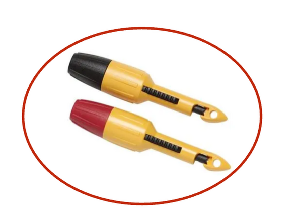
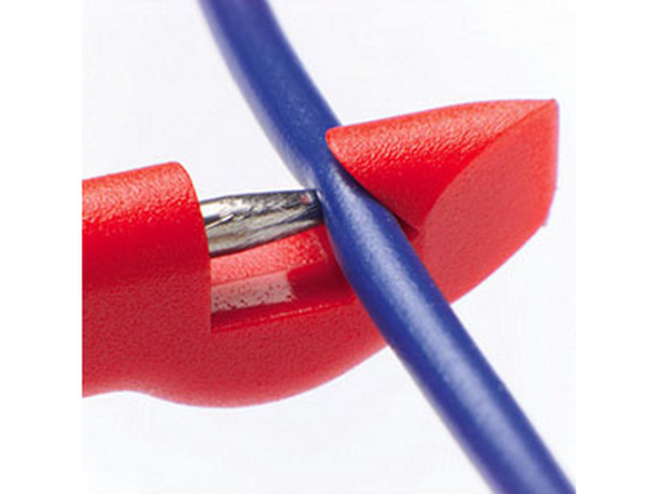
We recommend using a multimeter with insulation piercing clips to test the wires without damaging them.
-
-
-
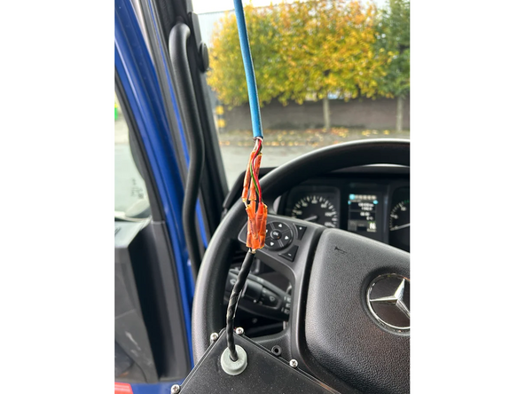
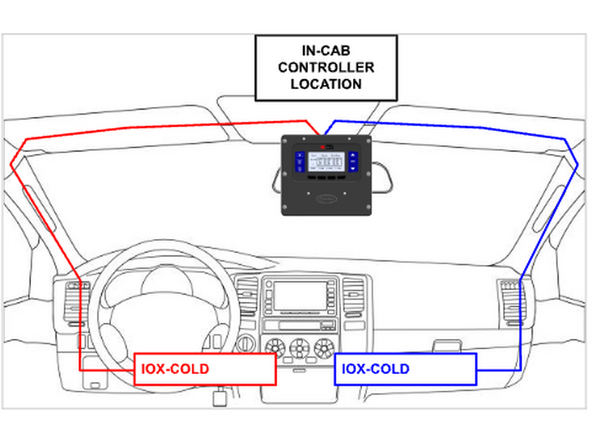
Route the HRN-CCCAAPX to the in cabin controller location.
-
✱ NOTE : If the in-cab controller is located near the rear view mirror, route the HRN-CCCAAPX through the vehicle’s cabin columns (right or left, depending on where the IOX-COLD and GO devices will be installed and connected). This ensures the cables won’t interfere with normal vehicle operation.
-
-
-
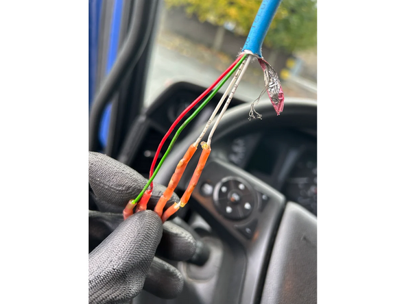
For this step, you’ll need to connect three wires on harness HRN-CCCAAPX to the refrigeration unit wires identified in step 3.
-
Vehicle ignition must be OFF for this step.
-
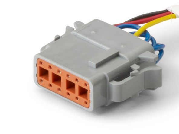
Make the following connections:
-
Connect the orange wire on HRN-CCCAAPX to the ground wire identified in Test and Identify Connections section.
-
Connect the yellow wire on HRN-CCCAAPX to the CAN high wire identified in Test and Identify Connections section.
-
Connect the blue wire on HRN-CCCAAPX to the CAN low wire identified in Test and Identify Connections section.
-
Protect all the connections with adequate material (i.e. heat shrink).
-
-
-
The HRN-CCCAAPX has additional wires which allows for connecting the IOX-COLD to additional sensors, such as 1-wire temperature sensors or door sensors.
-
If the customer requests these additional sensor connections, see Cold Chain installation - accessories . If not, go to the next step.
-
Once the HRN-CCCAAPX routing and connections are completed and all required connections are made, connect it to the GO device as described in the IOX-COLD quick start guide .
-
-
-
Switch the vehicle ignition and the in-cab controller ON to validate the installation.
-
! IMPORTANT: It is mandatory for every installation to use the MyInstall tool (requires a provisioned MyAdmin account) to configure the installation. If you do not do this, the device may not transmit the correct data.
-
You need a secure MyAdmin login to use this tool. If you do not have one, refer to the Creating MyInstall Credentials section of the MyInstall user guide.
-