Introduction
The GO Focus Pro supports up to 4 TVI auxiliary cameras, enabling 360-degree surround and blind spot monitoring. Side cameras mount to the vehicle mirror arm or a pole/J-bar bracket and provide coverage of adjacent lanes and blind spots alongside the vehicle. A rear camera mounts at the top-center of the vehicle rear wall and provides coverage directly behind the vehicle.
All auxiliary camera feeds are recorded through the GO Focus Pro and are accessible in the Geotab Video app for live viewing, playback, and angle adjustment. Optionally, a Zero-Latency Monitor can be added to display live camera feeds inside the cab as a real-time blind-spot monitor.
WARNING: Before drilling any holes or selecting permanent mounting locations, review and obtain approval from the customer. Drilling is irreversible — confirm the chosen locations will not interfere with vehicle structure, wiring, or the customer’s operational requirements before proceeding.
Recommended Tools & Consumables
Hardware & Accessories
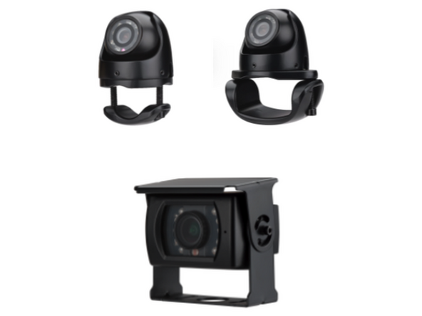
- HDW-EXTCAM-TVISB - GO Focus Pro - External Aux Side Cam - Small Bracket - TVI
- HDW-EXTCAM-TVILB - GO Focus Pro - External Aux Side Cam - Large Bracket - TVI
- HDW-EXTCAM-TVISQ - GO Focus Pro - External Aux Rear Cam - TVI
- HRN-TVICAM-5EXT - GO Focus Pro - Extension Cable - 5m / 16ft - TVI
- HRN-TVICAM-10EXT - GO Focus Pro - Extension Cable - 10m / 32ft - TVI
-
-
Before installing, determine best mounting location with customer for each side camera
-
There are two common mounting options:
-
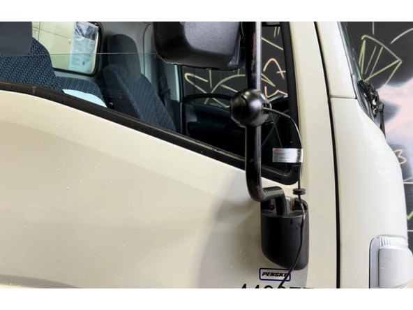
Small Bracket — The most common option. The camera clamps directly onto the existing mirror arm.
-
Large Bracket — Used for modular style mirror brackets.
-
Consider sight lines, cable routing access, and the customer's preferences when choosing the location.
-
Confirm the mounting location with the customer before drilling or permanently mounting any hardware.
-
-
-
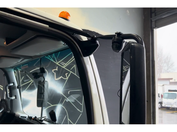
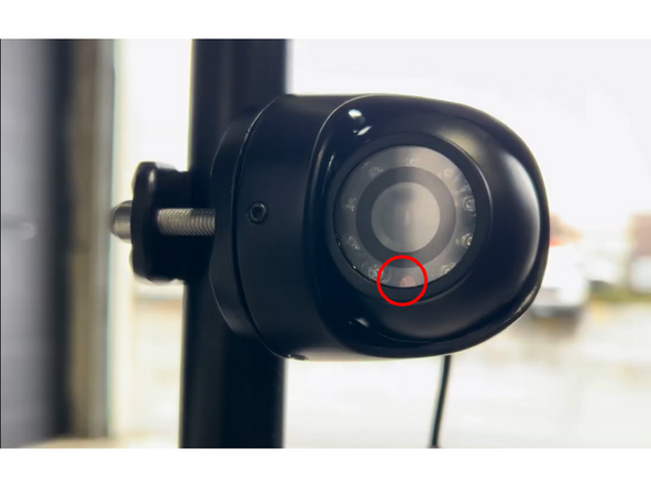
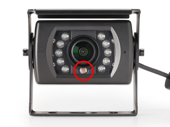
Before mounting, orient the camera so the sensor (lens) faces downward toward the ground.
-
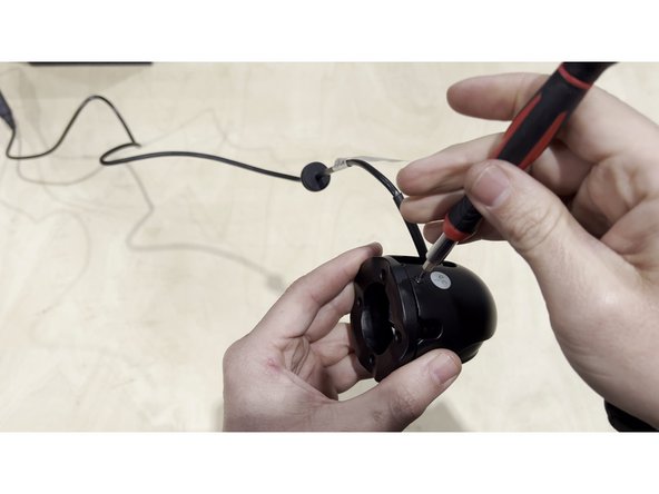
Loosen the allen screws around the camera body using an allen key to allow the camera to rotate freely within the bracket.
-
Rotate the camera until the lens points toward the ground, then re-tighten the allen screws securely.
-
Critical: An upward-facing sensor will produce an inverted image. Always confirm the sensor is pointing down before tightening.
-
-
-
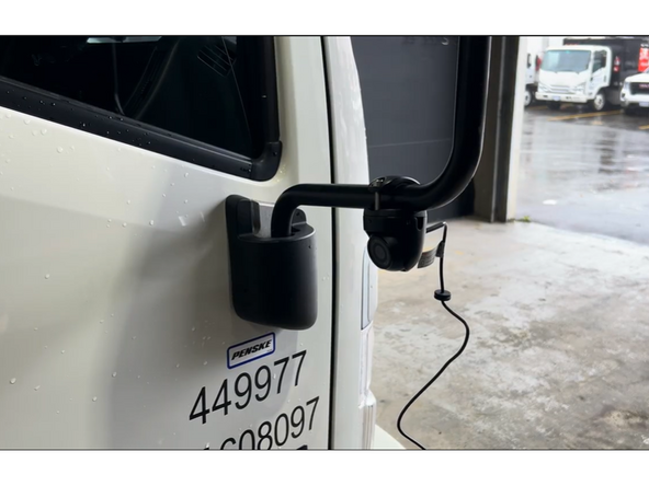
Slide the camera bracket clamp around the mirror arm (or pole mount) and position it at the desired height.
-
Hand-tighten the clamp bolt to hold the bracket in place temporarily — do not fully tighten yet.
-
Ensure the bracket arm extends outward so the camera will have a clear side-facing view.
-
Use the Small Bracket for narrower mirror arms and the Large Bracket for wider profiles.
-
-
-
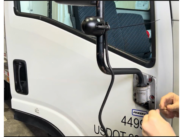
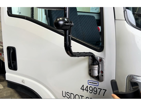
Starting at the camera, run the coax cable down the length of the mirror arm toward the cab.
-
Secure the cable to the mirror arm at regular intervals using zip ties. Keep the cable snug against the arm to prevent wind vibration.
-
Where the cable crosses a flex joint or hinge point, leave a small loop of slack to absorb movement without stressing the connector.
-
Protect exposed wire with loom.
-
-
-
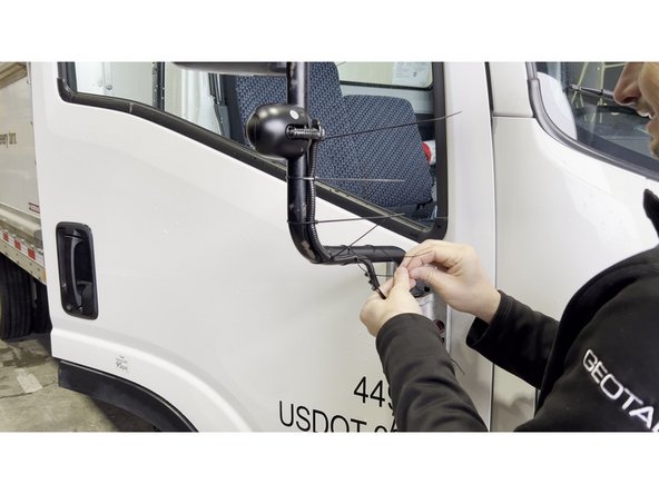
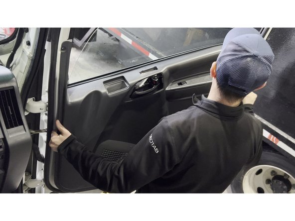
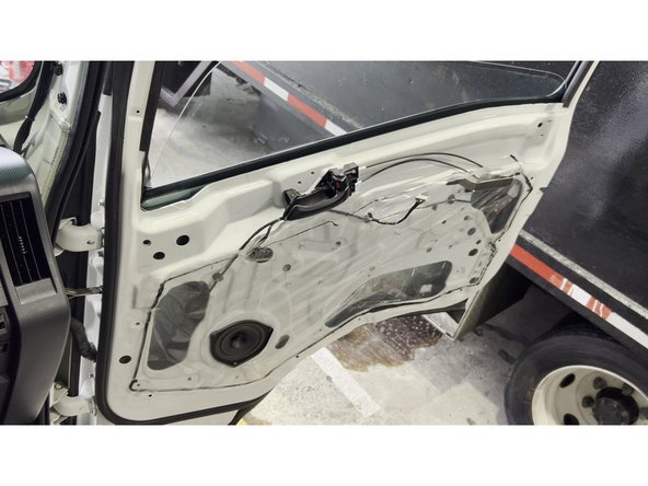
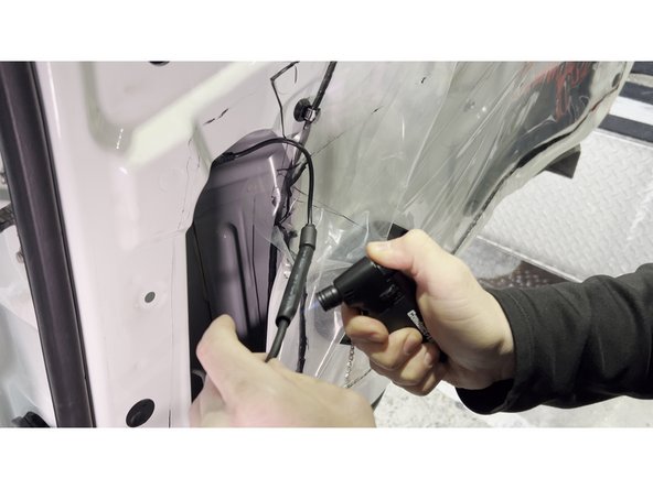
Open the cab door and remove the interior door panel to access the cable routing channel inside the door shell. Start by prying around the panel edges with a trim removal tool, then lift the panel upward to disengage the upper clips before pulling it fully away from the door.
-
On some vehicles, additional exterior or pillar panels may need to be removed to create a clear path for the cable. Remove only what is necessary to run the cable cleanly.
-
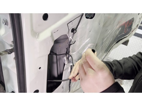
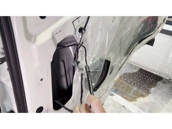
Peel back the factory plastic vapor barrier (poly sheeting) carefully — avoid tearing it, as it will be re-sealed when the panel goes back on.
-
Feed the camera coax cable from outside the door, through the door shell opening (where the exterior cable enters), and down through the interior of the door cavity toward the bottom of the door route with existing wiring.
-
If no factory grommet or pass-through exists: Obtain customer approval before drilling a new hole. Use the provided rubber grommet and seal with silicone sealant after routing the cable.
-
-
-
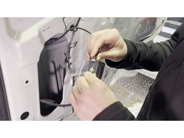
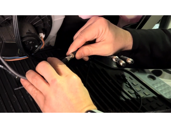
Inside the door cavity, connect the camera coax cable to the extension cable that will run to the GO Focus Pro. Before joining the connectors, apply a small amount of dielectric grease to the male coax pin to prevent corrosion at the connection point.
-
Thread the connector together and hand-tighten, then give a quarter-turn with a screwdriver to ensure a secure, weatherproof mechanical connection.
-
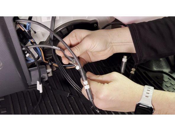
Use heat shrink tubing over the joined connection. .
-
Route the extension cable through the factory wiring harness door boot inside the door/pillar, securing with zip ties at regular intervals. Keep the connection point positioned within the door cavity where it will be protected from moisture and movement.
-
Re-seal the plastic vapor barrier with butyl tape or the original adhesive, then reinstall the door panel by re-engaging all clips and pressing firmly until seated.
-
-
-
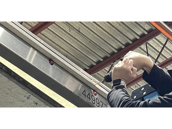
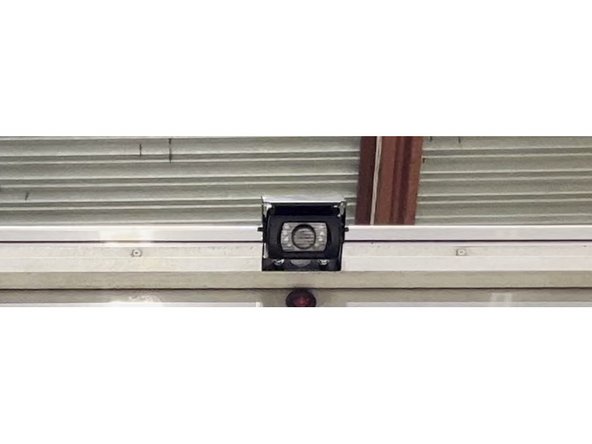
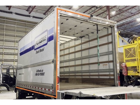
Mount the rear auxiliary camera at the top-centre of the vehicle’s rear wall or above the rear doors, using the included bracket.
-
Position the camera so the lens has a clear, unobstructed view of the area directly behind the vehicle.
-
Tighten all mounting bolts securely. The camera must not move or vibrate during vehicle operation.
-
For box trucks and vans, a ladder or lift may be required to safely reach the mounting location.
-
Critical: An upward-facing sensor will produce an inverted image. Always confirm the sensor is closest to the ground pointing downward before tightening.
-
-
-
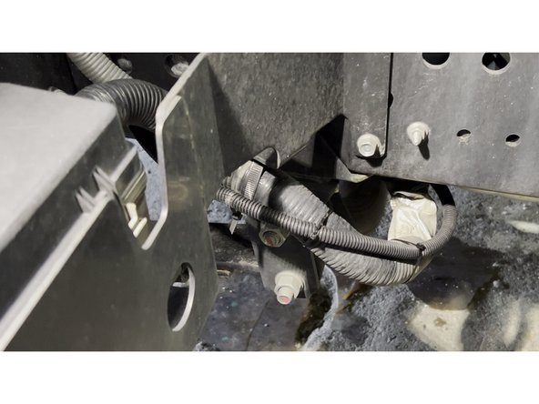
Run the rear camera cable along the vehicle frame from the rear mounting point toward the cab, keeping it tight against the chassis.
-
Protect the entire exterior cable run with wire loom and secure with zip ties every 30 cm (12 in).
-
Route the cable through existing factory grommets where available to maintain a weatherproof seal into the cab.
-
Keep all exterior cable runs away from exhaust components, sharp edges, and moving suspension parts.
-
-
-
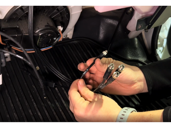
Feed the aux camera cables into the cab.
-
Locate the HUB Cable (Quad) from GO Focus Pro. Connect each aux camera coax cable to a HUB cable output:
-
-
-
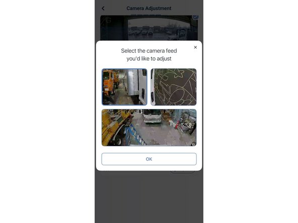
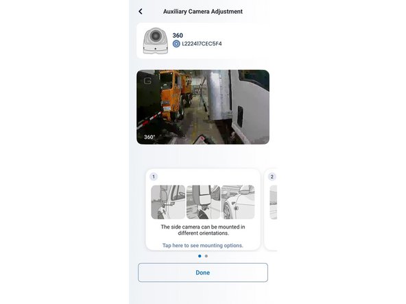
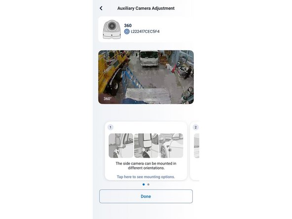
In the Geotab Video app, tap Camera Adjustment. When the dialog appears, tap one of the auxiliary side camera feeds to open its Auxiliary Camera Adjustment screen.
-
With a second person loosening the camera bracket bolt outside, adjust the camera angle while watching the live feed. Aim so the view shows:
-
The rear tire visible at the bottom of the frame.
-
The side of the vehicle along one edge of the frame.
-
1 to 2 lanes of the road extending outward from the vehicle.
-
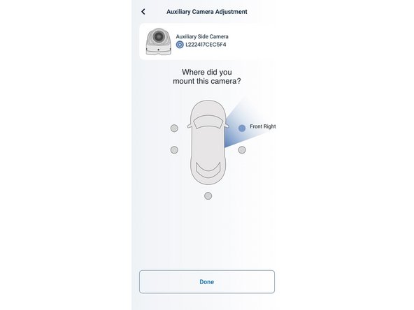
Tighten the bracket bolt and tap Done. When prompted with Where did you mount this camera?, tap the correct position (Front Left or Front Right) and tap Done.
-
Repeat for the second side camera.
-
-
-
Return to Camera Adjustment and select the rear auxiliary camera feed. Tilt the camera downward so the view shows:
-
A portion of the rear of the vehicle (bumper or rear doors) at the top of the frame.
-
The road surface filling the rest of the frame, showing vehicles approaching from behind.
-
Tighten the bracket bolt, tap Done, then assign the position as Rear Center on the vehicle diagram.
-
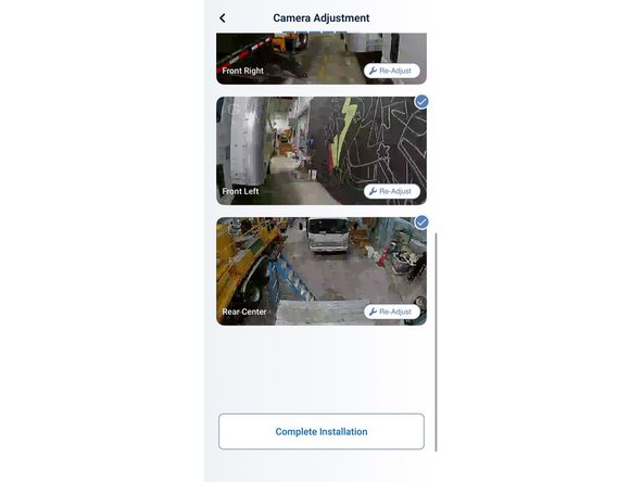
The Camera Adjustment summary screen will show all three auxiliary feeds -- Front Right, Front Left, and Rear Center -- each confirmed with a checkmark.
-
Tap Re-Adjust on any camera at any time to fine-tune the angle without restarting the full setup.
-