
Recommended Tools & Consumables
Hardware & Accessories
-
-
WARNING! Only use Geotab telematics devices with Geotab-approved harnesses acquired from Geotab-authorized channels. Use of non-Geotab harnesses from unauthorized channels can cause serious safety risks, including fire, and can lead to serious personal injury and/or damage to the vehicle.
-
IMPORTANT: Always use a vehicle-specific harness when offered by Geotab or the vehicle manufacturer to avoid possible damage to the GO device. Some vehicles have multiple diagnostic connectors to choose from when installing a GO device.
-
For more information on Geotab harnesses and adapters, refer to the Harness Identification and Application & Harness Assessment Cheat Sheet & Geotab Truck Solution - Harness Identification and Application
-
If a longer length is required to facilitate installation, connect a straight harness to a T-harness. Ensure that the total harness length does not exceed 2 meters (6.5 feet), because this can compromise the integrity of the data and cause issues with the vehicle’s Engine Control Unit (ECU).
-
For more details on compliance information and applicable products, contact your Authorized Reseller.
-
-
-
WARNING! Some installations are not straightforward and must be completed by an Authorized Installer to ensure a secure installation.
-
An unsecure device can result in poor electric and/or data connections, which can lead to short circuits and fires or cause malfunctions of vehicle controls that can result in serious personal injury or significant damage to the vehicle. Some examples requiring professional installation from an Authorized Installer are:
-
The OBD port location is such that the device protrudes and interferes with entering or exiting the vehicle, or located where it could be inadvertently kicked or bumped during vehicle operation.
-
The device isn't fully secured and so may come loose with vibrations or accidental contact.
-
An electrical harness or additional wiring is required.
-
Vehicle mounting modifications are required to secure the device, i.e. removing of panels; deformed/damaged OBD connector; or physical damage to the electrical wiring.
-
The device does not power on and beep six times when first installed.
-
The installer questions their ability to complete a secure installation according to these instructions.
-
-
-
WARNING! Do not attempt to install, reconfigure, or remove any product from a vehicle while the vehicle is in motion or otherwise in operation. All installation, configuration, or removal must be done only in stationary vehicles which are securely parked.
-
Attempting to service devices while the vehicle is in motion could result in malfunctions or collisions, leading to death or serious personal injury.
-
-
-
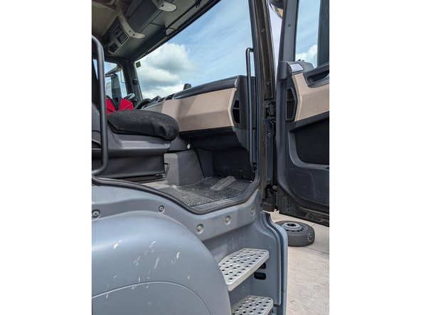
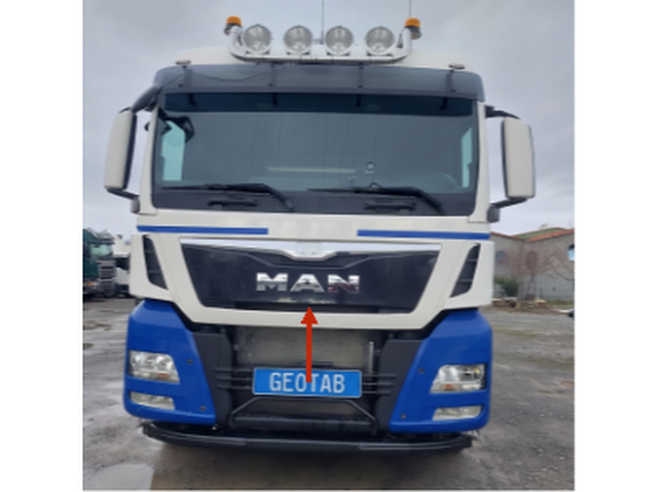
Access vehicle's fuse box is located on the passenger side.
-
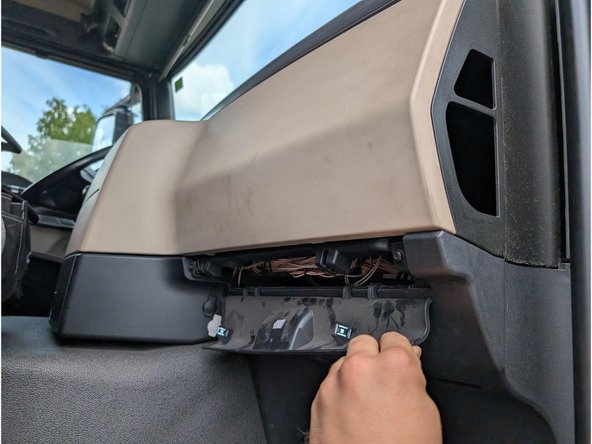
Gently pull the lower panel downward.
-
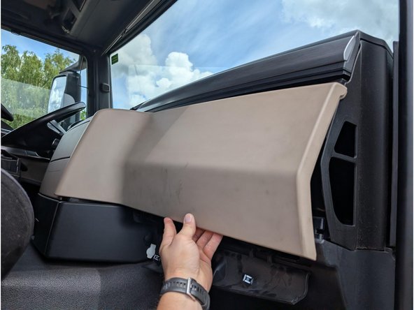
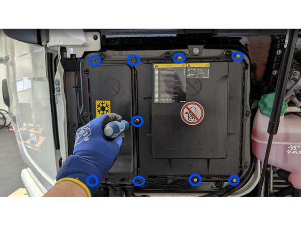
Unclip and remove the top panel of the dashboard.
-
-
-
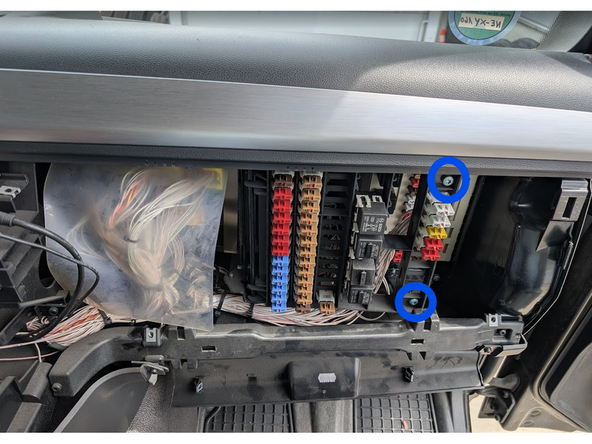
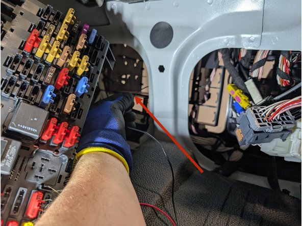
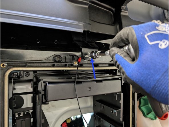
Once the cover has been removed, attach the black wire of the HRN-CW03K3-A harness to the specific screw shown in the photo using a suitable ring terminal.
-
-
-
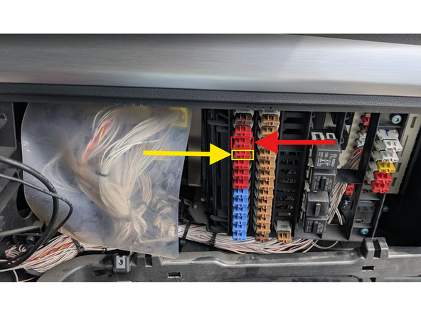
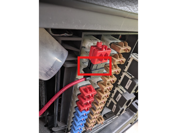
Continuous Power: Connect the red wire from the HRN-CW03K3-A harness to Fuse F429 (marked with a Red Square) using a fuse tap.
-
Use a Multimeter to confirm.
-
Place the original fuse on the hot side of the fuse tap. Insert a second fuse in the second slot as following:
-
Fuse F429 10 A
-
-
-
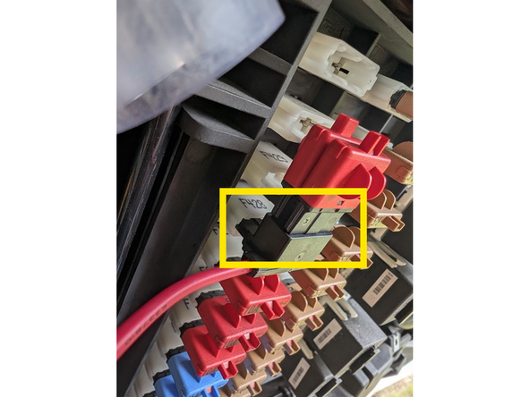
Ignition Power: Connect the yellow wire from the HRN-CW03K3-A harness to Fuse F428 (marked with a Yellow Square) using a fuse tap.
-
Use a Multimeter to confirm.
-
Place the original fuse on the hot side of the fuse tap. Insert a second fuse in the second slot as following:
-
Fuse F428 10 A
-
-
-
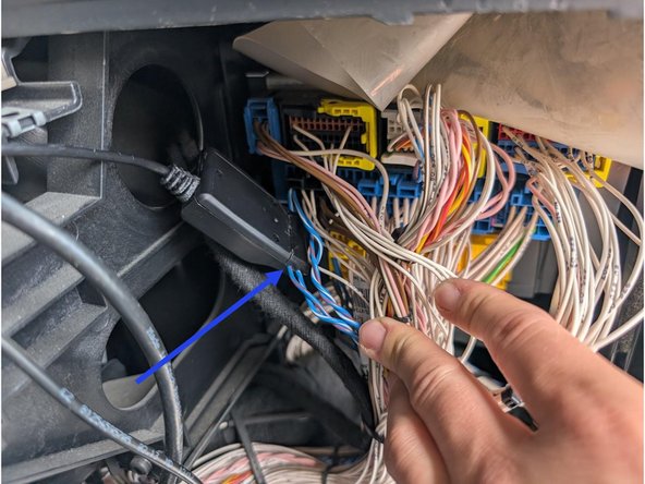
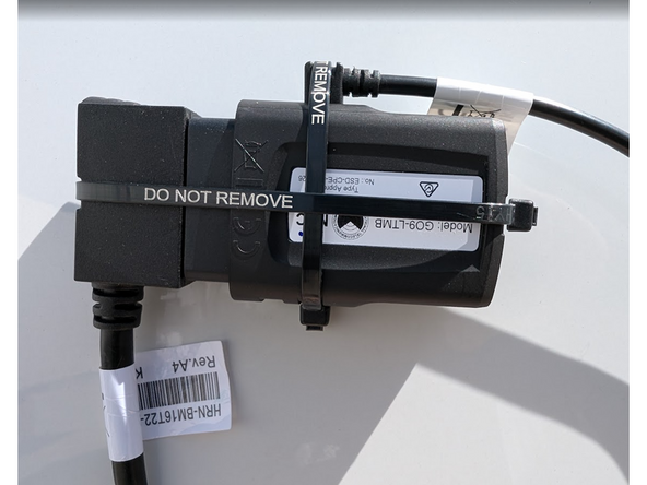
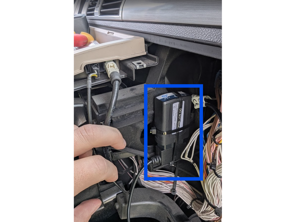
Once all three LEDs turn solid and you hear 10 quick beeps, secure the device using the provided cable tie. Ensure there is always a 20cm separation between the driver and the device. This applies to all users of the vehicle.
-
✱ NOTE : The device is considered installed when the Green and Blue LEDs turn solid.
-
-
-
All in-vehicle devices and related cabling must be securely fastened and kept clear of all vehicle controls, airbags, and gas, brake and clutch pedals.
-
This requires the use of a cable tie when securing the device or any extension harness to the OBD connector, securing both sides of the harness. If you do not use a cable tie, vibration in the vehicle can lead to a loose connection which could cause the vehicle’s engine computer to fail, causing potential loss of vehicle control and serious injury.
-
Inspect devices and cabling regularly to ensure all devices and cabling continue to be securely attached.
-
If at any point after an in-vehicle device is installed a warning light illuminates on the vehicle dash or the vehicle stalls or has a marked drop in performance, shut off the engine, remove the device, and contact your reseller. Continuing to operate a vehicle with these symptoms can cause loss of vehicle control, and serious injury.
-
-
-
Navigate to one of the following:
-
-
-
Note that the following steps are for the public version of MyInstall.
-
If you have an installer MyAdmin account, use this link
-
This link is also accessible via the MyInstall Public page.
-
-
-
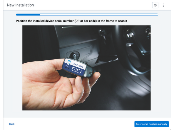
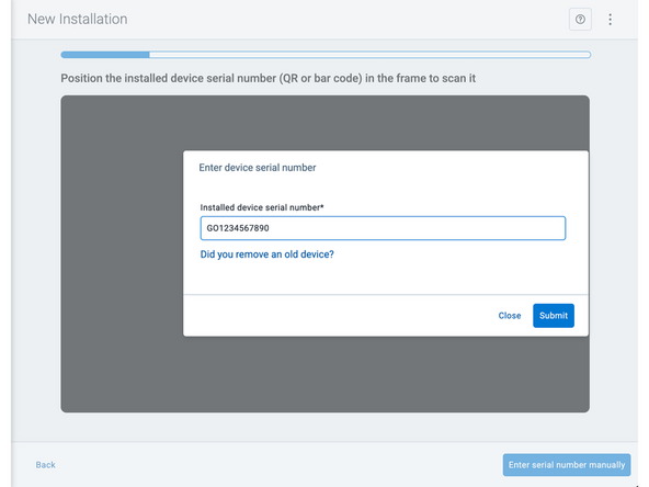
Two options are available to enter the device serial number:
-
Scan the device serial number (QR or barcode) using your mobile device.
-
Press Enter serial number manually, enter the serial number, and then press Submit.
-
If you are also removing an old device, press Did you remove an old device? and then enter the removed device serial number.
-
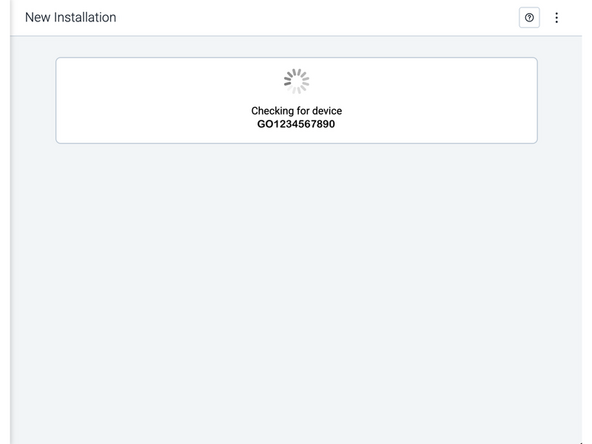
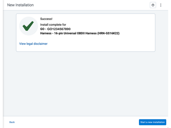
MyInstall takes a moment to check the device status.
-
-
-
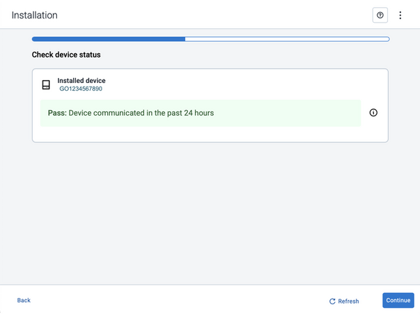
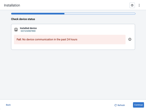
Installed device
-
Pass – The device has successfully communicated with the network in the last 24 hours.
-
Fail – The device has not communicated with the network in the last 24 hours.
-
If the device status shows as FAILED, verify the LED status and turn the ignition / engine off and on again.
-
Press Refresh to check the status again.
-
Refer to the MyInstall User Guide for detailed instructions.
-
-
-
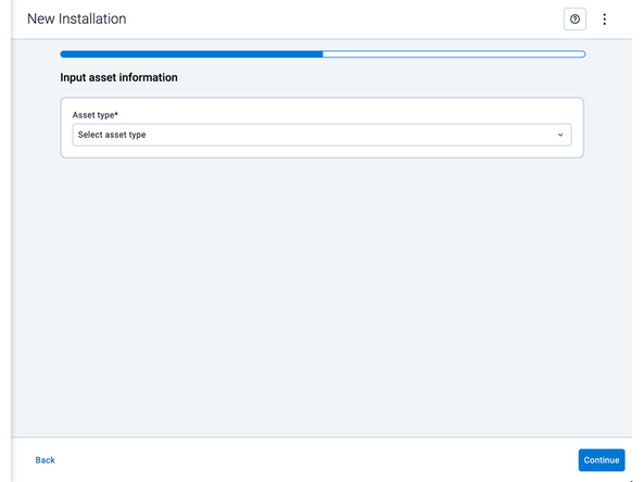
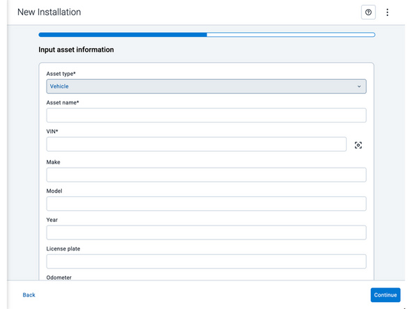
Asset name — Enter the vehicle or asset name. This field is mandatory.
-
VIN — Scan or enter the vehicle identification number (VIN). For scanning, select the scan icon [O] beside the field. This field is mandatory.
-
Make, Model, and Year — This information will be auto populated when you scan or enter a valid VIN. If it is not autopopulated, enter the information manually. NOTE: For some vehicle makes and models, the autopopulate option might not be possible.
-
License plate — Enter the vehicle license plate.
-
Odometer — Enter the vehicle odometer, and select the measurement unit (km or miles).
-
Engine hours — Enter the vehicle engine hours.
-
Camera ID (GO device only) — Scan or enter the installed camera identification (ID) number. NOTE: Depending on the camera type, the camera ID number can also be the camera’s International Mobile Equipment Identity (IMEI), or serial number. Select the information icon ⓘ to learn more about your camera’s ID number.
-
Work order reference — If applicable, enter a work reference number that is associated with the installation.
-
-
-
For the latest version of the Limitations of Use
-
Your in-vehicle devices must be kept clear of debris, water and other environmental contaminants. Failure to do so may result in units malfunctioning or short-circuiting, which can lead to a fire hazard and cause loss or serious injury.
-
This product does not contain any user-serviceable parts. Configuration, servicing, and repairs must only be made by an authorized reseller or installer. Unauthorized servicing of these products will void your product warranty.
-
The simplified EU declaration of conformity referred to in Article 10(9) shall be provided as follows:
-
Hereby, Geotab (Address: 2440 Winston Park Drive, Oakville, Ontario L6H 7V2, Canada, Phone number: 1 (877) 436-8221) declares that the radio equipment type ‘telematics device’ is in compliance with Directive 2014/53/EU. The full text of the EU declaration of conformity is available here.
-
WARNING: Cancer and Reproductive Harm
-



Team
